Progress so far all boards built up but no wiring yet
Just going to be using a 4 input selector for now that I already had built up
PS not sure about the transformer as they are only 25VA each, ? are they adequate ?
Alan
Those 25VA Talema are potted but they should be efficient enough also. You will judge from their cases temperature under load. The preamp is heavily biased Class A and it will massage them fast enough to a plateau. Up to 40C with the lid closed should be nice, and if reaching 40-50C hot enough but not alarming yet. You may still stick sinks on them if they will go too hot for your liking. Your box is tall enough. There are thermal adhesives for such jobs I believe.
By the way your arrangement looks very orderly and the box very sturdy, roomy, and modernly nice.
Progress so far all boards built up but no wiring yet
Just going to be using a 4 input selector for now that I already had built up
PS not sure about the transformer as they are only 25VA each, ? are they adequate ?
Alan
Alan,
What kind of potentiometer are you using for the volume? Looks like a big sturdy one.
Alan,
What kind of potentiometer are you using for the volume? Looks like a big sturdy one.
Look like it is Khozmo step attenuator.
Alan,
What kind of potentiometer are you using for the volume? Looks like a big sturdy one.
Yes its the Khozmo 25K Stepped Attenuator, fabulous quality and you can buy it in Shunt, ladder or Series configuration.
I normally use a 25K Goldpoint Stepped attenuator, but I bought this Khozmo a few years ago and have never tried it, so now is its chance

High Quality Audio & Industrial Attenuators and Passive Preamplifiers
Alan
Those 25VA Talema are potted but they should be efficient enough also. You will judge from their cases temperature under load. The preamp is heavily biased Class A and it will massage them fast enough to a plateau. Up to 40C with the lid closed should be nice, and if reaching 40-50C hot enough but not alarming yet. You may still stick sinks on them if they will go too hot for your liking. Your box is tall enough. There are thermal adhesives for such jobs I believe.
By the way your arrangement looks very orderly and the box very sturdy, roomy, and modernly nice.
Salas
Thanks I am just waiting for a few bits then I will fire it up for testing
eekand will measure the temp on the trannys, if necessary they can be replaced
Alan
Some small progress
Front panel drilled for the LEDs, On/Off switch and headphone socket fitted
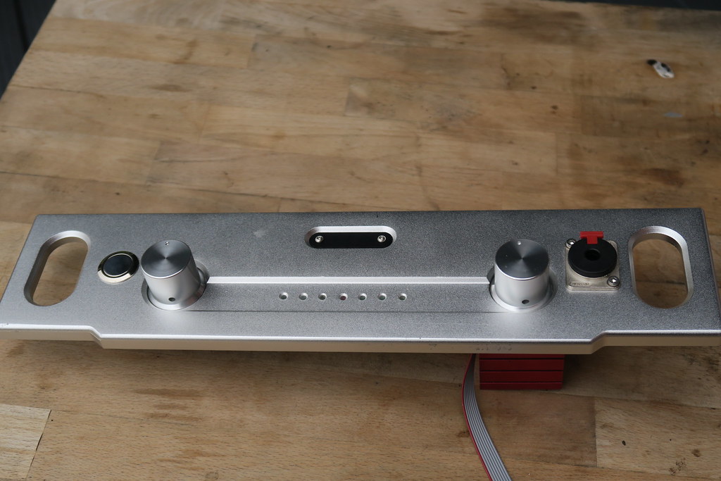 IMG_3060 by Alan Towell, on Flickr
Made up an LED mounting board
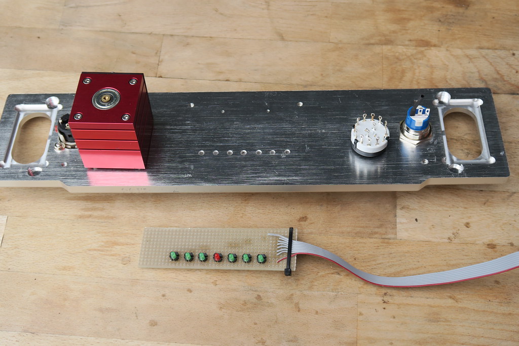 IMG_3050 by Alan Towell, on Flickr
Base board drilled for permanent mounting of circuit boards
 IMG_3038 by Alan Towell, on Flickr
Alan
Front panel drilled for the LEDs, On/Off switch and headphone socket fitted
IMG_3060 by Alan Towell, on FlickrMade up an LED mounting board
IMG_3050 by Alan Towell, on FlickrBase board drilled for permanent mounting of circuit boards
IMG_3038 by Alan Towell, on FlickrAlan
Simplest method is NA2MPMF | Neutrik
For switching at balanced realm there are relay boards configured for that. For same number of relays half the number of inputs.
Without SE to BAL transformer (or special chip) most obvious difference is balanced sources remaining twice stronger than alike SE sources.
For balanced input selection, is there any reason you couldn't wire up two I-Select boards using a 2 pole selector switch (half wired to PCB 1 and half to PCB 2) and a 4 gage potentiometer?
I have tested my DCG3 today and fortunately it didnt blow up
Right channel
Bias - 133.4ma (10R)
Voltage rails 17.05/ 17.06
DC Offset 0.3mv
PS Heat sink temp 34C
Output Transistors 28 - 34C
Transformers lid off 24C
Left channel
Bias - 132.4 ma (10R)
Voltage rails 17.17 / 17.07
DC Offset -0.5mv
PS heat sinks 38C
Output transistors 28 - 36C
Transformer lid off 24C
 DC Offset by Alan Towell, on Flickr
Alan
Right channel
Bias - 133.4ma (10R)
Voltage rails 17.05/ 17.06
DC Offset 0.3mv
PS Heat sink temp 34C
Output Transistors 28 - 34C
Transformers lid off 24C
Left channel
Bias - 132.4 ma (10R)
Voltage rails 17.17 / 17.07
DC Offset -0.5mv
PS heat sinks 38C
Output transistors 28 - 36C
Transformer lid off 24C
DC Offset by Alan Towell, on FlickrAlan
I have tested my DCG3 today
Alan
Clockwork
Yes its the Khozmo 25K Stepped Attenuator, fabulous quality and you can buy it in Shunt, ladder or Series configuration.
I normally use a 25K Goldpoint Stepped attenuator, but I bought this Khozmo a few years ago and have never tried it, so now is its chance
High Quality Audio & Industrial Attenuators and Passive Preamplifiers
Alan
That thing is like a work of art. Maybe it should be outside the box.
Today I have connected up 1 input to and Output and headphone out.
I still havent made a audio ground to case ground?, where is the best place to do that in this pre amp.
 IMG_3181 by Alan Towell, on Flickr
 IMG_3182 by Alan Towell, on Flickr
I still havent made a audio ground to case ground?, where is the best place to do that in this pre amp.
IMG_3181 by Alan Towell, on Flickr
IMG_3182 by Alan Towell, on FlickrMaybe from PSU zero to a standoff's screw of its PCB. Not to be drilling for test moves. Or XLR pin1 to its chassis screw. Or nowhere, only the pot's metal neck contacting the mains earthed chassis. Best is to use FFT and find lowest harmonic noise grounding for any build's specific config. Also testing for when interconnected to other gear.
Maybe from PSU zero to a standoff's screw of its PCB. Not to be drilling for test moves. Or XLR pin1 to its chassis screw. Or nowhere, only the pot's metal neck contacting the mains earthed chassis. Best is to use FFT and find lowest harmonic noise grounding for any build's specific config. Also testing for when interconnected to other gear.
Had a look at it with the scope this morning and it was quietest when connected to a power supply ground at the connector to the DCG3
Alan
I have an I-Select kit but the holes for the inputs are tiny and I couldn't reliably get the Kimber cable to crimp into the tiny pins.Alan,
How do you plan to select the source? I-select? Can see some parts but not the board itself.
so I have ordered one of these
ELECTRONICS-SALON 6 Channel Unbalanced Stereo or Balanced Mono Audio Input Selector Relay Module. ELECTRONICS-SALON A-130, ELECTRONICS-SALON MD-A130
Alan
Had a look at it with the scope this morning and it was quietest when connected to a power supply ground at the connector to the DCG3
Alan
At which one connector?
The holes in the I-Select board are to small to take the Kimber cable, in fact any cable that I have that I would use for an audio signalYou could alternatively solder the signal wires to the selector board since you already had one
Alan
- Home
- Source & Line
- Analog Line Level
- Salas DCG3 preamp (line & headphone)