I connected the left channel HP GND to the pot GND and then the right channel HP GND to a CL60 (yellow green cable) and terminating at the chassis GND.
That's a loop. Connecting the same ground lane to chassis twice on different points. Disconnect the CL60 route and see what happens.
Lets clarify that the pot to chassis grounding is meant as continuity of its metal face and threaded neck to chassis. Its signal GND pin should continue from the input RCA GND to the PCB's Input GND through the coaxial signal wiring's shield.
Just thinking, how is the ground loop created? There is only one return path to rhe chassis ground via the CL60.
Because you wrote there are two paths. One to the CL60 another to the pot's GND. Unless you meant something different than the pot's body.
What would be the best way to incorporate single-ended inputs into a fully balanced pre-amp? I.e. to provide for switching between one or two single-ended inputs and a few balanced inputs into a fully balanced pre-amp with balanced outputs (I am less concerned about single-ended outputs). It looks like the relay can only handle SE switching.
I have seen pre-amps use input transformers to convert the single-ended signal at the inputs - you would then have all balanced signals, but would still need to switch between them. I'm also not sure if an input transformer is ideal.
I have seen pre-amps use input transformers to convert the single-ended signal at the inputs - you would then have all balanced signals, but would still need to switch between them. I'm also not sure if an input transformer is ideal.
Simplest method is NA2MPMF | Neutrik
For switching at balanced realm there are relay boards configured for that. For same number of relays half the number of inputs.
Without SE to BAL transformer (or special chip) most obvious difference is balanced sources remaining twice stronger than alike SE sources.
For switching at balanced realm there are relay boards configured for that. For same number of relays half the number of inputs.
Without SE to BAL transformer (or special chip) most obvious difference is balanced sources remaining twice stronger than alike SE sources.
Case ventilation
Case ventilation has been frequently mentioned especially since we are fond of using high heat generating shunt regs.
Should there be more openings at the bottom or at the top? Or is there some desired ratio that promotes airflow from bottom to top much like a chimney?
If we were to attach the shunt transistors to the case bottom then heat would be transferred from them to the case mostly by conduction and the case would then radiate to the outside air, so would ventilation really help here? On the other hand using DCSTB style sinks heat is transferred by radiation and convection so ventilation should be necessary.
Also does the distortion and THD strata of the DCG3 change significantly as the case gets really hot?
Any thoughts?
nash
Few holes around the place of bottom attached MOSFETS with corresponding holes at the top augments convection for the direct to chassis method with shunts. In DCSTB's case few holes directly above the board level sinks helps. The THD spectra changes a little with heat but not much.
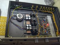
Having a look at my layout to decide what chassis to order and can’t decide if I should use both of these transformers, or if I should save space by using a single one. What would I sacrifice by going single?
Attachments
Last edited:
I don't know, never listened to a DCG3 build other than with twin trafos. To use single trafo for two diode bridge inputs it should have four sets of secondaries i.e. double the now secondary wires. Else, a mono shared supply must be also used. DCSTB board is V grooved in the middle to can be easily separated in mono bipolar units.
I don't know, never listened to a DCG3 build other than with twin trafos. To use single trafo for two diode bridge inputs it should have four sets of secondaries i.e. double the now secondary wires. Else, a mono shared supply must be also used. DCSTB board is V grooved in the middle to can be easily separated in mono bipolar units.
Thanks Salas!
I had the PSU for my power amp in mind, which is completely different, and mixed things up.
The reason for mixing things up in the first place was that I'm not sure how to connect the 18+18 leads from the transformers. On my power amp that's quite forward. (Or at least I thought so until now...
 )
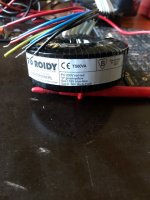
)230V is red+red and earth is green/yellow, but 18V sec1 is blue-blue and 18V sec2 is black-black. At Toroidys homepage I can't find anything but simple drawings, not saying anything about how the 18+18 go together. They look so neatly arranged that I guess that the blue and the black next to each other go together. But guessing worries me a bit...
Anyone who has used these transformers for the DCSTB and can tell how they should be connected? Or am I making things more complicated than they are?
Attachments
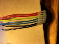
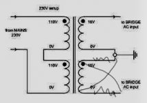
Connect blue with black and measure the other black with blue if is ac 36v. If not connect the other black with the same blue and measure again
I think you'll find that the wires on Toroidy's come out in order so to speak so the inner blue and black connect together to put the windings in series. But as oracle1 says check with your dmm.
Thanks a lot! I thought that must be the most logical way. But how could I tell if i got 36V, but connected “the wrong way”?
Sharing same secondaries between two bridges... Does the trafo or bridge diodes get any hot? Or is there some hum?
There is noway 36v if it is the wrong way
It could be connected with one pair switched. But I don’t know if it would make any difference?
Attachments
Last edited:
- Home
- Source & Line
- Analog Line Level
- Salas DCG3 preamp (line & headphone)