Well, there were different versions of the PSU...Hello @Carl_Huff et al.,
as I'm working on my own IO board and other stuff (RIAA preamp + a rotary encoder based on an MCU) for this preamp, I'd like to know if someone knows (or know how to calculate) the maximum mA I can ask from the PSU designed by Carl. On my lab PSU I'm currently seeing between 260-280mA with all the pieces running.
Many thanks for any informations concerning this.
Raph
Assuming you have the version with the bugfix summarized here, the transformer should be the limiting part, i.e. ~400mA for the 15VA version, ~700mA for the 25VA version. Be careful as there are no secondary fuses on the PCB, afaik.
Looking at power dissipation of the output transistors: The rectifiers will output +-18V*1.4=+-25V DC. If you use +-15V at the outputs of the supply, there will be a dissipation of (25V-15V)*output current, i.e. 4W for 400mA. Shouldn't be a problem, I guess, depending on your heat sink.
Well, there were different versions of the PSU...
Assuming you have the version with the bugfix summarized here, the transformer should be the limiting part, i.e. ~400mA for the 15VA version, ~700mA for the 25VA version. Be careful as there are no secondary fuses on the PCB, afaik.
Sorry I did not precise it at first, that's definitely this one I'm using.
Looking at power dissipation of the output transistors: The rectifiers will output +-18V*1.4=+-25V DC. If you use +-15V at the outputs of the supply, there will be a dissipation of (25V-15V)*output current, i.e. 4W for 400mA. Shouldn't be a problem, I guess, depending on your heat sink.
Wow! Many thanks for the insights, definitely what I was looking for.
Best to all.
The sound of silence
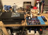
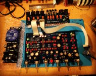
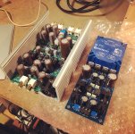
It works! Thanks to everyone on this thread, especially Carl and Doug, I have arrived at the point in my build where this thing actually plays music.
First impression is that this is one quiet preamp. And does it sound good! My first listening test was far from ideal, but I did prove that, a. It works, and b. It didn’t blowup or burn down the house - two good signs in any build.
The images show the boards completed and connected to each other; the preamp connected to a test setup on my bench; lastly, I thought I would show off the Douglas Self/Signal Transfer Co. phono preamp I built at the same time. I used one of Carl’s PSUs to power it.
Next step is to box it up. I’m debating 1U or 2U, deciding knob choices, and planning how I want my silkscreens laid out front and back.
Attachments
Good news: It will be a few months, but the BC550CTA will be back in stock at Mouser.
Not so good news: the BC560CTA is no longer carried. Alternatives?
Endless stock:
Security Check
Last edited:
Good news: It will be a few months, but the BC550CTA will be back in stock at Mouser.
Not so good news: the BC560CTA is no longer carried. Alternatives?
BC337 ?
Hm, when using XLR inputs, 4 relays need to be driven simulaneously, i.e. 4*12mA=48mA. Current through the 1st BC550 is limited by the 47k resistor, i.e. 14V/47k=0.3mA. This means that the 2nd BC550 needs an hFE of at least 160@50mA. Looking at Fig.3 in the datasheet of the BC337-40, it *should* work, but it's close...BC337 ?
https://www.onsemi.com/pdf/datasheet/bc337-d.pdf
2SC2240 should work.BC550C is low noise NPN, hFE~500.
BC560 is PNP.
BC337 is NPN, 800 mA, general purpose.
In place of BC550C, try 2SC1845 or 2SC2240. For the PNP. their complementary pair.
To drive a relay with higher gain, I use BC517 (NPN, darlington).
2SC1845 is limited by maximum collector current of 50mA and hFE (s. Fig.3 in https://cdn-reichelt.de/documents/datenblatt/A100/SC1845-FSC.pdf).
Both have different pinouts.
Noise doesn't matter for the relay drivers.
I would recommend a Darlington, too. Or use the two BC550 as a Darlington
")
Again, hFE... I'd recommend the B or C types.BC546 will work great here .
Correction: It's 11V, not 14V, so the required hFE is ~200.Hm, when using XLR inputs, 4 relays need to be driven simulaneously, i.e. 4*12mA=48mA. Current through the 1st BC550 is limited by the 47k resistor, i.e. 14V/47k=0.3mA. This means that the 2nd BC550 needs an hFE of at least 160@50mA. Looking at Fig.3 in the datasheet of the BC337-40, it *should* work, but it's close...
https://www.onsemi.com/pdf/datasheet/bc337-d.pdf
I was just checking them out. Any appreciable difference between the “CTA” end suffix and the “B” versions?I bought the BC550 and BC560 from Tayda Electronics.
I was just checking them out. Any appreciable difference between the “CTA” end suffix and the “B” versions?
I believe the CTA is the SOT package, whereas the B is a TO-92. This build uses the TO-92 package.
Rear Panel FPD or DWG Files?
Hello Builders,
Does anyone have Rear Panel FPD or DWG Files? I have Carl’s fpd files for the front panel (1U/2U), but I haven’t found these files for the rear and would like to avoid having to draw them myself if possible.
Thanks in advance!
Hello Builders,
Does anyone have Rear Panel FPD or DWG Files? I have Carl’s fpd files for the front panel (1U/2U), but I haven’t found these files for the rear and would like to avoid having to draw them myself if possible.
Thanks in advance!
Rear Panel FPD file
glenv6,
Here is a rear panel layout for a 1U case. I cannot remember who sent it to me, so thank you whoever you are.
Dropbox - REAR_PANEL_1U.fpd - Simplify your life
glenv6,
Here is a rear panel layout for a 1U case. I cannot remember who sent it to me, so thank you whoever you are.
Dropbox - REAR_PANEL_1U.fpd - Simplify your life
Here is the one I drew.
https://www.diyaudio.com/forums/att...g-self-preamp-linear-audio-5-a-rear-panel-pdf
https://www.diyaudio.com/forums/att...g-self-preamp-linear-audio-5-a-rear-panel-pdf
- Home
- Source & Line
- Analog Line Level
- Doug Self Preamp from Linear Audio #5