The display says: maya_1_6_oled-bp.
I have checked and rec checked and checked again the volCB board, but I cannot find anything wrong. It gets the 5 volt on the two PCF85741.
What could be wrong? Is the PCF85741 of some reason defective?
Got the Bluetooth working , thanks, and the channel numbers are now correct. Is there anywhere a users manual to Maya? or do I have to read all the threads to get the information?
Hi koldby,
so the issue is : it seems that volCB and Maya do not work together.
And you say that they stay at 5V.
Can you put and oscilloscope on SDA and SCL lines from Maya to see if there is something output from Maya ?
If the Maya controller outputs on the lines when you modify volume or input then the fail is on volCB board.
Did you connect SCL from Maya to SCL from volCB and SDA from Maya to SDA from volCB and ground to ground ?
Please test with oscilloscope on SDA and SCL lines from Maya without connecting volCB board and share the result.
User manual and info :
vicol audio : MAYA - world best stepped volume attenuator
https://www.vicol-audio.com/img/maya/Maya algoritm2.pdf
Last edited:
Nothing out of the Maya when I change volume or input, stays at 5 V. All connections are routed correct I have keyed connectors with colour coding on number 1 pin. so I am sure this is correct.
With a scope on both the SCL and SDA when powering up Maya, they just goes to +5V , with or without the volCB connected
With a scope on both the SCL and SDA when powering up Maya, they just goes to +5V , with or without the volCB connected
Nothing out of the Maya when I change volume or input, stays at 5 V. All connections are routed correct I have keyed connectors with colour coding on number 1 pin. so I am sure this is correct.
With a scope on both the SCL and SDA when powering up Maya, they just goes to +5V , with or without the volCB connected
If this is the case and you are sure 100% then
you need to return Maya for check /service.
Did you purchase this from vicol-audio site ?
If so please contact Tibi and me on the email from the site .
vicol audio : contact
so... trying to get the bppbp to play... all is soldered in but on channel I get nothing but noise, and when I open the valume passed half way, DC offset increasing with 'volume'. the DC is not present on the output of U2/A, only the output of U2/B shows this. Would anyone have an idea where to start searching?
Thanks,
Rob
Thanks,
Rob
Thanks for the prompt reply Jan!
Given the amount of time I have it will be slow going... .
The DC offset thing is one channel only. But both channels look noisy on the scope (pico scope to laptop on batteries). The interesting thing is... they're noise with or without power applied. Which makes me think I might have to review grounding. I have connected the centertap of the transformer to safety ground, and I see a lot of noise on the scope when measuring between two points connected to ground. Maybe I'll start there... .
With no power applied, Relay K3 will keep the output short circuited.
So when there's noise to be seen on your scope with no power, this has little to do with grounding.
What amount of noise do you see coming from your PicoScope when connecting the hot side of your probe to the ground strap.
Hans
So when there's noise to be seen on your scope with no power, this has little to do with grounding.
What amount of noise do you see coming from your PicoScope when connecting the hot side of your probe to the ground strap.
Hans
Some Measurements...
Hi,
Finally managed to collect some first measurements. (a lot to learn, posting inline images for one...)
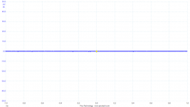
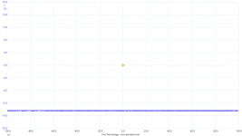
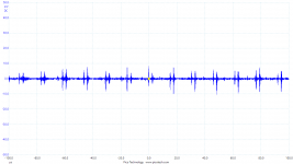
1. probe hot pin and ground strap shorted. Doesn't look much different from groundstrap and hot pin floating.
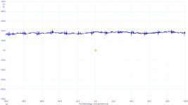
plugged in, with no power applied (ground connected to safety earth, line and neutral interupted):
2. Ground to pin 3, similar image on both channels and for both pin 2 and pin 3)
3. Pin 2 to pin 3. looks similar as ground to pin 2/3 but higher amplitude
looks like interference from something my desktop pc connected to the same circuit.
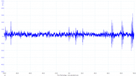
Power on, input shorted:
4.-7. At low volume, a similar image as before, but higher amplitude, with increasing volume nothing really happens until somewhere passed 60%. left channel gets negative DC offset, right channel positive.
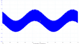
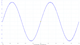
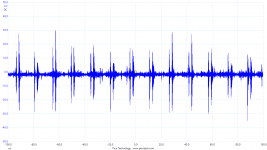
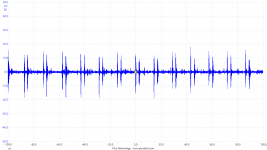
Applying a signal to the input:
8-10: with low volume, the signal is present and amplified, but seems noisy, rotating the volume pot increases the volume at the output untill somewhere 80% when I get something that looks like oscilation to me.
Next I'll work my way back as Jan suggests. Are there any tricks to connect a probe safe and reliably to an smd opamp output? Just a steady hand?
Best regards,
Rob
Hi,
Finally managed to collect some first measurements. (a lot to learn, posting inline images for one...)
1. probe hot pin and ground strap shorted. Doesn't look much different from groundstrap and hot pin floating.
plugged in, with no power applied (ground connected to safety earth, line and neutral interupted):
2. Ground to pin 3, similar image on both channels and for both pin 2 and pin 3)
3. Pin 2 to pin 3. looks similar as ground to pin 2/3 but higher amplitude
looks like interference from something my desktop pc connected to the same circuit.
Power on, input shorted:
4.-7. At low volume, a similar image as before, but higher amplitude, with increasing volume nothing really happens until somewhere passed 60%. left channel gets negative DC offset, right channel positive.
Applying a signal to the input:
8-10: with low volume, the signal is present and amplified, but seems noisy, rotating the volume pot increases the volume at the output untill somewhere 80% when I get something that looks like oscilation to me.
Next I'll work my way back as Jan suggests. Are there any tricks to connect a probe safe and reliably to an smd opamp output? Just a steady hand?
Best regards,
Rob
Attachments
-
 shorted.png16.7 KB · Views: 478
 -
 left_1k_sin_vol_high.png30.4 KB · Views: 69
 -
 left_1k_sin_vol50.png25.1 KB · Views: 84
 -
 Left_1k_sin_vol_low.png38.5 KB · Views: 70
 -
 Right_power_on_input_shorted_volume100.png21.3 KB · Views: 70
 -
 Right_power_on_input_shorted_vol85.png39.7 KB · Views: 73
 -
 left_input_shorted_max_volume.png17.2 KB · Views: 464
 -
 left_power_on_input_shorted_low volume_03.png46.2 KB · Views: 470
 -
 Pin2_Pin3_power_off.png36.9 KB · Views: 474
 -
 Ground_to_pin_3_power_off.png25.9 KB · Views: 473
Hi,
Finally managed to collect some first measurements. (a lot to learn, posting inline images for one...)
1. probe hot pin and ground strap shorted. Doesn't look much different from groundstrap and hot pin floating.
plugged in, with no power applied (ground connected to safety earth, line and neutral interupted):
2. Ground to pin 3, similar image on both channels and for both pin 2 and pin 3)
3. Pin 2 to pin 3. looks similar as ground to pin 2/3 but higher amplitude
looks like interference from something my desktop pc connected to the same circuit.
Power on, input shorted:
4.-7. At low volume, a similar image as before, but higher amplitude, with increasing volume nothing really happens until somewhere passed 60%. left channel gets negative DC offset, right channel positive.
Applying a signal to the input:
8-10: with low volume, the signal is present and amplified, but seems noisy, rotating the volume pot increases the volume at the output untill somewhere 80% when I get something that looks like oscilation to me.
Next I'll work my way back as Jan suggests. Are there any tricks to connect a probe safe and reliably to an smd opamp output? Just a steady hand?
Best regards,
Rob
Rob,
In your previous email you mentioned that you were using a laptop running on batteries.
Is this laptop still connected to a mains charger or is it completely disconnected from mains ?
With no power applied, figure 2 shows a 50Khz signal, typical for a SMPS.
This could be the Laptop charger, but anyhow, this signal is most likely picked up through your probe's ground lug.
With power applied, you show a signal coming through.
Is this for the working channel or for the defective channel.
And yes to keep things stable, don't turn the volume too far, no further than 6dB gain to start with or oscillation may occur.
First try to get a clean signal from the preamp. You could even use four 9Volt batteries to power the preamp, to have a fully floating test setup.
Begin with checking whether all IC's are mounted the right way and not turned by 180 degrees. Then check if all IC's are having a stable +/- 12 Volt on their pins.
And yes, as a next step follow Jan's suggestion and compare both channels to each other and see where they start to differ, with and without an input signal applied.
Measuring SMD Amps can be done with a steady hand, but you can also put the scope on a resistor connected to the relevant SMD pin. That will be more safe.
Succes, Hans
I forgot to update on this. The Maya was sent to Vicol and they found no errors on the controller. So after I got it back I rechecked my VOLcb and noticed that the PCF8574's I had mounted on the boards was without the "A" suffix. I investigated a little on the difference, and it appears that the adresse structure differ a little. So I ordred new PCF8574, now in the "A" version and substituted the old plain PCF8574 with the new PCF8574A. Bingo!If this is the case and you are sure 100% then
you need to return Maya for check /service.
Did you purchase this from vicol-audio site ?
If so please contact Tibi and me on the email from the site .
vicol audio : contact
Everything worked now, and have done that ever since

So be very careful when ordering PCF8574
Thanks to Tibi and Danzup for excellent support!
Thanks to
I'm late to the party I know, but I've managed to get my hands on a bare BPBP PCB. However, I've had no luck trying to find a BOM. Anyone?
I am using the BOM linked on this page:
Bruno Putzeys Balanced Preamp - Group Buy Part 3
One thing I found: R8 etc. is actually the same as R19 etc. I hadn’t noticed that, so ticked it off my list while having ordered 4 instead of the 8 that are needed...
Last edited:
I am using the BOM linked on this page:
Bruno Putzeys Balanced Preamp - Group Buy Part 3
One thing I found: R8 etc. is actually the same as R19 etc. I hadn’t noticed that, so ticked it off my list while having ordered 4 instead of the 8 that are needed...
Thank you.
I'd also like to build Hans' VolCB volume controller. Are the PCBs available anywhere with a BOM?
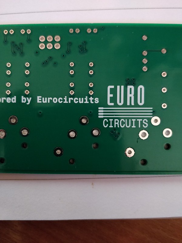
I'm finding it impossible to get anything through Net-Ties J4 and 10 on the boards I have and the lands aren't too great either. For connecting the VolCB board, can I use alternative points to connect the GNDs?
See point 6
Attachments
Thank you Hans. All I need now is to get my hands on a VolCB PCBSee point 6
I had 10 bare PCBs made for my own use, I have built one and it works fine. I only require 1 input and didn't use the on-board psu section or the XLR connectors.
I don't need the other 9 PCBs and they might be useful to someone. Therefore I am offering them at 3euro each plus postage (using standard letter post only).
The PCBs are 1oz ENIG (Electroless Nickel/Immersion Gold) and made by Seeedstudio Fusion.
These are bare PCBs with no components soldered or provided.
- Home
- Source & Line
- Analog Line Level
- BPPBP - Bruno Putzey's Purist Balanced Preamp (well a balanced volume control really)