Don't touch calibration relays. My code does not use them for mute, but they are still used for calibration. You need to take the one for power on delay instead and use it as second output relay. See pin definitions and compare them to original code, that will give you an idea.
Ok thanks but maybe its easier and cleaner if I can order a current 4x2 board from you? I could use some extra inputs.
Ok thanks but maybe its easier and cleaner if I can order a current 4x2 board from you? I could use some extra inputs.
Can't argue with that 😉
I still have few boards with relays left, very likely the last batch I ever made. They also have the ability to be driven with single 12V stabilized power supply.
Last edited:
How much does a board with relay cost?
It's 45 eur plus 5 eur shipping.
I still have few boards with relays left, very likely the last batch I ever made. They also have the ability to be driven with single 12V stabilized power supply.
Are these bare boards or partly built ?.
Are these bare boards or partly built ?.
PCBs with relays soldered in.
I figured out why latest Arduino IDE breaks IR - it's the timing in newPulseIn function:
return clockCyclesToMicroseconds(width * 29 + 16);
this line needs to be changed to:
return clockCyclesToMicroseconds(width * 22 + 16);
Repeat will still not work after this, so further changes to be made are these:
//if (duration == 0) // This is an error no start or end of pulse
// return (255); // Use 255 as Error
if (repeat && (c4 == 2) or repeat && (c4 == 1)) // Only way to verify a repeat from this remote is with the 2 code?
Now we can all switch to latest IDE.
You made an awesome work on that project zdr.
Thanks a lot.
I use it for a few month now and I can say it's very convenient to use.
Thanks a lot.
I use it for a few month now and I can say it's very convenient to use.
Have you corrected at your google drive shared files?
So far only VxD_OLED1602_4X2 has been corrected.
I figured out why latest Arduino IDE breaks IR - it's the timing in newPulseIn function:
return clockCyclesToMicroseconds(width * 29 + 16);
this line needs to be changed to:
return clockCyclesToMicroseconds(width * 22 + 16);
Repeat will still not work after this, so further changes to be made are these:
//if (duration == 0) // This is an error no start or end of pulse
// return (255); // Use 255 as Error
if (repeat && (c4 == 2) or repeat && (c4 == 1)) // Only way to verify a repeat from this remote is with the 2 code?
Now we can all switch to latest IDE.
Looks like some of my hacks @zdr?
Looks like some of my hacks @zdr?
No idea, did I step on parts of your code? 🙂
No idea, did I step on parts of your code? 🙂
I recall having to hack those bits for a different IDE version when I first built it. I recall using a 1khz square wave to try and recalibrate the software based timing code. The repeat code was also troublesome and was based on codes returned by the remote in debug mode. A weakness of this design is that the remote code is not interrupt driven.
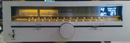
Hey there,
here is another casing option for the LDR controler, i put it i an old Tuner Case and i think it fits quite well.
might not be for everyone but i like the "classic" look.
The big knob drives the encoder (and still the tuning bar 🙂)
The fm mode Button does the same thing as pushing the encoder.
i dont seem to be able to find how to dim the display, i used the latest 4x2s code.
And there is a font included in the file, modern_h which only cosists of numbers, does anyone have the matching (size24x32) letters?
Thanks!
Attachments
Hey there,
here is another casing option for the LDR controler, i put it i an old Tuner Case and i think it fits quite well.
might not be for everyone but i like the "classic" look.
The big knob drives the encoder (and still the tuning bar 🙂)
The fm mode Button does the same thing as pushing the encoder.
i dont seem to be able to find how to dim the display, i used the latest 4x2s code.
And there is a font included in the file, modern_h which only cosists of numbers, does anyone have the matching (size24x32) letters?
Thanks!
NICE! No letters, sorry.
Thanks Neb!
the extra size of the tuner case also allows me to put the crossover and my two Sub-Amps in there.
The Letters are not really that important, just a nice to have...
I wanted to use Kapital letters instead of the input number. like PC,BT,
I also tried to include Fonts from the Adafruit_GFX.h Library, but thats above my skill level with arduino.
Do you have an idea why my Display is not fading?
it always stays lit fully, i used your latest code for Oled_4x2s, the Display is same as the one you posted earlier in this thread. IDE is 1.6.9, but my board is not your newest V3, i got the "previous" Rev.
You put an amzing amout of work into this!
Thanks again for all your help!
J
- Home
- Source & Line
- Analog Line Level
- Arduino based LDR volume and source selection controller