I've integrated the controller in my Hypex amplifier, with excellent results. Instead of using the rotary controller, I'm using a serial connection between the MCU already used in the amplifier to the LDR controller.The amplifier MCU is always on/standby, so it can be switched on by the remote, I'm looking into a way to set the controller to standby as well. To be more specific, I'd like to switch off the LDRs to prevent wear of the LDRs.
Is this even necessary? And if it is, how can I switch off (and switch on) the LDRs? I'm not sure if a setLSE(0); setLSH(0); setRSE(0); setRSH(0); is enough, or that I should also switch off the BIAS voltage. Also, there could still be output on the amplifier, so I must make sure the volume is muted.
Did anybody implement an off/standby for the LDR controller?
I've integrated the controller in my Hypex amplifier, with excellent results. Instead of using the rotary controller, I'm using a serial connection between the MCU already used in the amplifier to the LDR controller.The amplifier MCU is always on/standby, so it can be switched on by the remote, I'm looking into a way to set the controller to standby as well. To be more specific, I'd like to switch off the LDRs to prevent wear of the LDRs.
Is this even necessary? And if it is, how can I switch off (and switch on) the LDRs? I'm not sure if a setLSE(0); setLSH(0); setRSE(0); setRSH(0); is enough, or that I should also switch off the BIAS voltage. Also, there could still be output on the amplifier, so I must make sure the volume is muted.
Did anybody implement an off/standby for the LDR controller?
I'm not quite sure I understand the use case here. Under which circumstances would you want the power amp to run and LDRs to be off?
Either way, setXXX(0) stops current through the LDRs since MOSFET is not conductive at Vgs = 0, so there is no need for that.
Last edited:
I'm not quite sure I understand the use case here. In which circumstances would you want the power amp to run and LDRs to be off?
That is not what I want to achieve. I'd like to be able to switch on the amplifier as well as the LDR controller with my IR remote control. The amplifier and the LDR controller are in the same enclosure, and are sharing a power supply. I have implemented an MCU for the control of the amplifier, so I'm not using the IR, screen or rotary of the LDR controller. The amplifier modules can be turned on by using an enable pin. I could use a relay or a mosfet to turn on the LDR controller, but if I can turn off the LDRs, that is not necessary.
So far I came up with:
void switchOff()
{
state = STATE_OFF;
setCalibrationRelays(ON);
setLSE(0); setRSE(0);
setLSH(0); setRSH(0);
mcp.digitalWrite(PIN_EXT_BIAS, LOW);
setLSH_Range(LOW); setRSH_Range(LOW);
}
void switchOn()
{
mcp.digitalWrite(PIN_EXT_BIAS, HIGH);
setVolume(VOL_DEFAULT);
setCalibrationRelays(OFF);
state = STATE_RUN;
}
Did not test it yet though.
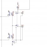
Because the 5LN01SP is no longer available in TO-92 package, and I haven't ordered the boards yet, I decided to try and replace them with an equivalent in SOT-23 (FDV301N).
Could someone please check if I made no huge errors? Had to rebuild copper plane and from what I see all pads that are supposed to go to ground still do, and I have no floating copper.


Could someone please check if I made no huge errors? Had to rebuild copper plane and from what I see all pads that are supposed to go to ground still do, and I have no floating copper.
Last edited:
There is no problem to make it work from the arduino point of view. You need to make sure it works from electrical perspective, as the load impedance will go down when you drive two inputs.
What would be the best way to wire up the LDR Controler ?
Can I use a tube amp with line-level inputs on the main Outputs and an active x-over with an input buffer stage (and maybe later replace it with a DSP)on the second Outputs?
Attachments
Thanks Neb,
i updated my device with the new code,
but i was also wondering if it is possible to change the function of the output relays slightly:
(using the LDR to switch my Subwoofer output (Relay6) on and off.)
If "Output1" is selectet i would like to switch on R5, and if "Output2 is selectet i would like to switch on both, Relay5 and Relay6.
do you think this works?
maybe i could get some help with the code?
in the function setOutput() i can find the two Output relays,
are these switched depending on the varable "chan_out"?,
what is the value in the byte "chan_out" when output 1 is selected?
Thanks!
maybe i could get some help with the code?
in the function setOutput() i can find the two Output relays,
are these switched depending on the varable "chan_out"?,
what is the value in the byte "chan_out" when output 1 is selected?
Thanks!
output 1 => chan_out = 0
output 2 => chan_out = 1
I did not mean it as a flame ignition, but as a tribute to Vincent77 who designed this awesome device and on top of that - offered it to community completely free of charge, instead of making tons of money. I'm sorry if you saw it any other way. So agreed, let's keep it nice (and awesome).
It's not a firmware issue, it's hardware design issue with original boards. All-in-one 4x2 boards have separate dedicated output relays that can mute without pop as they do not switch any DC (unlike calibration relays used for mute in original boards). There had to be a change in firmware to accommodate hardware change though.
The only remaining little annoyance is the volume "bump" when VxD is switching between low and high impedance mode. I compensated it as much as I could in the firmware, but it still can be noticed with white noise.
I didn't realise this. Thanks @ZDR. But I can't see how the calibration voltage can appear at the output as the relays must be break before make? Is it not more likley the pop is due to RE3 connecting the output to 0V on mute?
I didn't realise this. Thanks @ZDR. But I can't see how the calibration voltage can appear at the output as the relays must be break before make? Is it not more likley the pop is due to RE3 connecting the output to 0V on mute?
All I know is that there is no pop on my boards and they also mute outputs by connecting them to ground - the code just does not touch calibration relays for muting purposes. So I guess it must be the calibration circuit. It's not a good design anyway to flip the calibration during mute, but I guess it was due to limited number of relay control pins. I remember that someone in this thread blew up MCP23008 by flipping mute too often.
Also don't forget that entering calibration mode connects audio gnd with digital gnd, which is another bad idea during mute and a very good candidate for audio "pop".
Fully assembled kit with PS, rotary encoder, IR sensor + OLED: 200eur , with LCD: 180eur.
zdr,
I am Interested at your fully assembled kit.
Please confirm that I do not need to bother with arduino stuff - controller Is Included and programmed.
Can you offer ballanced stereo version.
zdr,
I am Interested at your fully assembled kit.
Please confirm that I do not need to bother with arduino stuff - controller Is Included and programmed.
Can you offer ballanced stereo version.
I confirm that everything is included, but there is no balanced version.
thank you for reply
do you plan to do balanced version
can user tape down new names for Inputs and outputs without pc
do you plan to do balanced version
can user tape down new names for Inputs and outputs without pc
No plans for the moment, I do not see enough interest. I/O names change require firmware re-upload in the current firmware.
In order to use In balanced system Is It possible to use arduino controller to controll not just one board but also another board, etc to double outputs from arduino controller
In order to use In balanced system Is It possible to use arduino controller to controll not just one board but also another board, etc to double outputs from arduino controller
You would need two complete boards with two Arduinos that are connected either over I2C or serial, one acting as master and other as slave, and significant coding effort to make everything work together.
All I know is that there is no pop on my boards and they also mute outputs by connecting them to ground - the code just does not touch calibration relays for muting purposes. So I guess it must be the calibration circuit. It's not a good design anyway to flip the calibration during mute, but I guess it was due to limited number of relay control pins. I remember that someone in this thread blew up MCP23008 by flipping mute too often.
Also don't forget that entering calibration mode connects audio gnd with digital gnd, which is another bad idea during mute and a very good candidate for audio "pop".
Thanks Neb! Could you perhaps share your current 4x2 schematic with me so I can modify my unit to be compatible with your firmware?
I’m afraid I don’t have schematics as I made mods on pcb layout only, but mod is simple: use two arduino pins instead of one controlling two separate output relays that can be used as mute instead of calibration relays. One pin is old output relay pin and the other was used to control power delay relay before.
I’m afraid I don’t have schematics as I made mods on pcb layout only, but mod is simple: use two arduino pins instead of one controlling two separate output relays that can be used as mute instead of calibration relays. One pin is old output relay pin and the other was used to control power delay relay before.
OK I had a look at your code. If I cut a track and run RE3 off Rel6 instead of Rel0 would that work with your code?
Attachments
Last edited:
OK I had a look at your code. If I cut a track and run RE3 off Rel6 instead of Rel0 would that work with your code?
Don't touch calibration relays. My code does not use them for mute, but they are still used for calibration. You need to take the one for power on delay instead and use it as second output relay. See pin definitions and compare them to original code, that will give you an idea.
- Home
- Source & Line
- Analog Line Level
- Arduino based LDR volume and source selection controller