Hi Maxw,
Your new diagram is also strange.CS pin (center pin of attenuator board is CS) should have to connect with pin 10. please check.
The pins of the input selector and attenuator in the pic are not in order. I made the diagram like this because it makes the wire path simpler.

I've updated the diagram so it's clearer.Hi Maxw,
Your new diagram is also strange.
please see the attached video clip. It's machine gun...
You are not turning the encoder, right? When it just changes randomly really fast it usually means one of the connections for the encoder is not correct. What model is it? Have you looked at the pin out of the encoder to be sure you have it connected right?
Hi maxw
I'm using the MCP23017 it is exactly the same as the MCP23S17 apart for the communication system I2C/SPI.
On the resistor side I was just a bit confused about your "bom", on the eijndhoven calculator I get; Rout-10k, R16-3.9r, R15-10K, R14-6.2r, R13-10K, R12-270r, R11-10K....
On your bom you have; Rout-10k, R16-6.2r,R15-10K, R14-270r,R13-10K, R12-1.8K, R11-10K...
It was does differences that were confusing me apart from that I have mine working but haven't done any boards yet still need to tweek a few things like encoder debounce and decide how to present the info on the screen, right now looks like a rats nest with wires all over the place.
It looks pin compatible with my PCB. Excellent!Hi maxw
I'm using the MCP23017 it is exactly the same as the MCP23S17 apart for the communication system I2C/SPI.
On the resistor side I was just a bit confused about your "bom", on the eijndhoven calculator I get; Rout-10k, R16-3.9r, R15-10K, R14-6.2r, R13-10K, R12-270r, R11-10K....
On your bom you have; Rout-10k, R16-6.2r,R15-10K, R14-270r,R13-10K, R12-1.8K, R11-10K...
If you use the eijndhoven calculator set to 10K, 0.5dB steps, E96 resistors, Constant input resistance and 8 stages you will get numbers that are very close to mine.
It was does differences that were confusing me apart from that I have mine working but haven't done any boards yet still need to tweek a few things like encoder debounce and decide how to present the info on the screen, right now looks like a rats nest with wires all over the place.
Sounds good. If you use a high quality encoder like Bourns EM14 or EN series they don't need debouncing.
I've updated the diagram so it's clearer.
You are not turning the encoder, right? When it just changes randomly really fast it usually means one of the connections for the encoder is not correct. What model is it? Have you looked at the pin out of the encoder to be sure you have it connected right?
Hi Maxw,
Yes I didn't turn the encoder on the video clip. But when i turned the encoder, it's still have no music or sound from attenuator board...
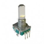
This is normal ALPS rotary encoder. Please see the picture attached,,
And I also find out the reference for this encoder, but I'm not sure it's for Arduino...
===========
Description:
This rotary encoder can be easily used with an interrupt handler routine. Please check out our open source sample code (free to use - without warranties of any kind, either expressed or implied).
Specifications:
• Encoder type: Alps
• Size Base: 11mm
• 15pulse/30position
• Diameter/length: 6/20mm
• Button function: yes
resources:
Code to use this encoder:
-----------------------------------------------------------------------------------------------------------------
// Alps Encoder
#define PINenc0a 2 // Rotary encoder0 pin a. 5v -> Encoder middle pin -> Right pin -> PINenc0a
#define PINenc0b 13 // Rotary encoder0 pin b. 5v -> Encoder middle pin -> Left pin -> PINenc0b
#define PINenc0but 5 // Rotary encoder0 button. 5V - Switch - Analog5 - 10k Ohm - Ground
#define ENC0changedelay 100 // Delay per change (steps of 100 uSeconds)
#define ENC0maxdelay 250 // Max total delay per interrupt (steps of 100 uSeconds)
volatile unsigned char ENC0=0; // Rotary encoder state
volatile unsigned char ENC0old=0; // Rotary encoder state
volatile int ENC0pos=0; // Rotary encoder position
int ENC0oldpos=0; // Rotary encoder old position
volatile unsigned char ENC0speed=1; // Rotary encoder accelleration
volatile char ENC0dir=0; // Rotary encoder direction
int ABenc0button()
{
return (analogRead(PINenc0but)>500);
}
// Rotary encoder interrupt 1 - Panasonic encoder - single interrupt
void ABenc0()
{
unsigned char pins;
unsigned long t1=0, t2=0;
while ((t1<ENC0maxdelay) && (t2<ENC0changedelay))
{
pins=digitalRead(PINenc0b)+(digitalRead(PINenc0a) << 4);
if (pins!=ENC0)
{
if ((ENC0==0x00) && (pins==0x10)) { ENC0pos-=ENC0speed; ENC0dir=1; }
if ((ENC0==0x10) && (pins==0x01)) { ENC0pos-=ENC0speed; ENC0dir=1; }
if ((ENC0==0x01) && (pins==0x10)) { ENC0pos-=ENC0speed; ENC0dir=1; }
if ((ENC0==0x11) && (pins==0x01)) { ENC0pos-=ENC0speed; ENC0dir=1; }
if ((ENC0==0x10) && (pins==0x00)) { ENC0pos+=ENC0speed; ENC0dir=1; }
if ((ENC0==0x01) && (pins==0x11)) { ENC0pos+=ENC0speed; ENC0dir=1; }
if ((ENC0==0x11) && (pins==0x00)) { ENC0pos+=ENC0speed; ENC0dir=-1; }
if ((ENC0==0x00) && (pins==0x11)) { ENC0pos+=ENC0speed; ENC0dir=-1; }
ENC0=pins;
t2=0;
}
delayMicroseconds(100);
t1++;
t2++;
}
}
void ABenc0setup()
{
// Encoder 0
pinMode(PINenc0a, INPUT);
pinMode(PINenc0b, INPUT);
attachInterrupt(0, ABenc0, RISING+FALLING);
}
void setup()
{
Serial.begin(9600);
Serial.print("Bootn");
ABenc0setup();
}
void loop()
{
Serial.print("Encoder position="); Serial.print(ENC0pos); Serial.print(" button="); Serial.print(ABenc0button());
Serial.println("");
delay(250);
}
Attachments
What code are you using? That code you just posted or my code?
Of course your latest code here.
https://github.com/FutureSharks/preamp-passive
Hmmm, OK.
Well, I think your encoder has either a poor connection or your grounding is bad or something. I've that exact thing before when this is the case. The attenuator just randomly changes very fast.
To test the attenuator to see if it actually works, do this:
1. Remove the encoder and any cables except the connection to the attenuator.
2. Remove
Code:
void loop() {
  blah blah
}
3. then add:
Code:
void loop() {
  delay(5000);
  setAttenuatorLevel(0);
  delay(5000);
  setAttenuatorLevel(128);
  delay(5000);
  setAttenuatorLevel(255);
}
Now this should just switch between 3 volume settings every 5 seconds.
Hi Maxw,
I've just tried your recommend test and it's work.
every 5 second, there are clicking sound from the attenuator board continuously. Is that mean the attenuator board have no problems?
If so, what should I have to do for next?? I tried two different encoder already... Is it from the different encoder from your so the code doesn't work for my encoder??
Great. The attenuator should click every 5 seconds and you should hear your signal at 3 different settings: silent, middle and high. If this is the case then the attenuator is fine.I've just tried your recommend test and it's work.
every 5 second, there are clicking sound from the attenuator board continuously. Is that mean the attenuator board have no problems?
I don't really know. I think you should focus on just trying to get the enoder to function normal on it's own. Try following all the examples here:If so, what should I have to do for next?? I tried two different encoder already... Is it from the different encoder from your so the code doesn't work for my encoder??
Arduino Playground - RotaryEncoders
And then when you have it working or solve the problem maybe you would need to change my code to suit.
Hi Maxw,
I found some error on the board.
when I tried to heard music with connected speaker, for the first time there was no sound even the relay clicking sound have been heard in every 5 seconds. So I've check again the board and your schematic. the input/out-put of your board should have to changed. It's mis-print I guess. I see your schematic again and I think I'm right. So I changed the input/output connect on the borard and I can heard the music finally.
So there is one serious question. Because input/output should have to change to opposite side, those all resistors should have to change their positon on the board also???
Second is for the value of resistors. In every 5 seconds, fist two steps(relays) volume level are same with my ears. Last step one is louder, but 1st & 2nd step have no difference.
Third is for the still encoder... when i tried to connect again my ALPS encoder, it still looks like machine gun... no changed...
but the difference, now I can heard the music even the volume rapidly/randomly increased, decreased with machine gun sound.
I hope your kindness Maxw... because I'm really beginner so It's will take a year to build up right code by myself...
Hope you check my report in your side.
BTW, Really still thanks for your sharing.
I found some error on the board.
when I tried to heard music with connected speaker, for the first time there was no sound even the relay clicking sound have been heard in every 5 seconds. So I've check again the board and your schematic. the input/out-put of your board should have to changed. It's mis-print I guess. I see your schematic again and I think I'm right.
So I changed the input/output connect on the borard and I can heard the music finally. So there is one serious question. Because input/output should have to change to opposite side, those all resistors should have to change their positon on the board also???
Second is for the value of resistors. In every 5 seconds, fist two steps(relays) volume level are same with my ears. Last step one is louder, but 1st & 2nd step have no difference.
Third is for the still encoder... when i tried to connect again my ALPS encoder, it still looks like machine gun
... no changed... but the difference, now I can heard the music even the volume rapidly/randomly increased, decreased with machine gun sound.
I hope your kindness Maxw... because I'm really beginner so It's will take a year to build up right code by myself...
Hope you check my report in your side.
BTW, Really still thanks for your sharing.
Last edited:
Hi Maxw,
I found some error on the board.
when I tried to heard music with connected speaker, for the first time there was no sound even the relay clicking sound have been heard in every 5 seconds. So I've check again the board and your schematic. the input/out-put of your board should have to changed. It's mis-print I guess. I see your schematic again and I think I'm right.
Sorry but I don't really understand where you think the mistake is
 Hi Maxw,
I'm sorry I misdeem the schematic. I mistaken the IC pin number which in the box as out side number. Sorry for make you confused.
One thing that very happy news for you.
I bought Bourns encoder from digikey and it have arrived this weekend.
Now the relarys working seemed perfect. Not anymore machine gun!
But would you make code for my alps encoder when you have a spare time??
because Bourns encoder quite expensive... It's hard to buy some more..
I want to use this Bourns encoder for your MDAC preamp building which my next project.
Anyway, for the sound test of passive attenuator board need more time because I have to rework for some chip resistors. I'll post again after rework on the board. Thank you!
Last edited:
View attachment 573714 Hi Maxw,
I'm sorry I misdeem the schematic. I mistaken the IC pin number which in the box as out side number. Sorry for make you confused.
One thing that very happy news for you.
I bought Bourns encoder from digikey and it have arrived this weekend.
Now the relarys working seemed perfect. Not anymore machine gun!
Great! Happy you got it sorted.
I can see why you were confused. One thing is the pin name and the other is the package pin number.
But would you make code for my alps encoder when you have a spare time??
Spare time? Unlikely
register valus..
Hi Maxw,
I tried passive attenuator with new encoder last day.
There is sound but it's strange.
The volume is repeate high & low. From the beginning to end of 256 steps, high & low repeated about 3 times.
I've changed all resistors for 2 time (actually 3times), it's same.
At the moment, I guess if relays working perfectly, it's the matter of resisters value... would you check again?? I'll record the sound and attache soon for your information.
It's the values form your BOM.
R1 560
R2 160000
R3 1100
R4 82000
R5 2000
R6 39000
R7 3600
R8 16000
R9 6200
R10 6800
R11 8200
R12 1800
R13 10000
R14 270
R15 10000
R16 6.2
Rout 10000
Hi Maxw,
I tried passive attenuator with new encoder last day.
There is sound
but it's strange.The volume is repeate high & low. From the beginning to end of 256 steps, high & low repeated about 3 times.
I've changed all resistors for 2 time (actually 3times), it's same.
At the moment, I guess if relays working perfectly, it's the matter of resisters value... would you check again?? I'll record the sound and attache soon for your information.
It's the values form your BOM.
R1 560
R2 160000
R3 1100
R4 82000
R5 2000
R6 39000
R7 3600
R8 16000
R9 6200
R10 6800
R11 8200
R12 1800
R13 10000
R14 270
R15 10000
R16 6.2
Rout 10000
- Status
- This old topic is closed. If you want to reopen this topic, contact a moderator using the "Report Post" button.
- Home
- Source & Line
- Analog Line Level
- Passive Preamp: Arduino based, remote control, Relay R2R, input selection