well, I guess I also had to do a passive attenuator, as well (lol):
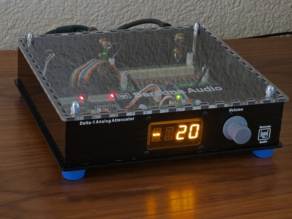
mostly just as a demo. I still prefer buffering but buffering adds dual rail power supply and other build complications. so, yeah, passive is a lot easier to build (lol).
using my delta-1 relay atten, an arduino nano running a modified version of lcduino/volumaster, an adafruit LED display and a rotary encoder.
Hi MaxW
I know this is over a year but I need some clarification...
In the R2R relay board you use the MCP23S17 and 2 ULN2803 and I wander why.
Is it really necessary to have 2 ULNs to drive the realays ?
Ric
Yeah because a MCP23S17 can only sink or source 25mA per pin. If you had relays smaller than that then it would be OK but then you would also need protection diodes too though (these are inside the ULN2803).
Hi
Thanks for the answer but I'm still a bit confused.
I read the datasheets for the MCP23X17 and for the the ULN2803
The 25mA from the MCP23S17 are enough to drive the ULN2803 and this one can supply 500mA in each pin and I think is more then enough to drive the small relays, I'm using Telecom relays from Nec and they only need around 160ma to latch and hold the contact.
My question was about this case if the ULN2803 can supply 500mA/pin why did you use 2 of them to drive the 8 relays (2xULN2803 are 16 drivers)
Sorry to be a pain but I like to understand the reason behind this
Ric
Hi
My question was about this case if the ULN2803 can supply 500mA/pin why did you use 2 of them to drive the 8 relays (2xULN2803 are 16 drivers)
Ah now I understand your question. The reason is that I am using latching (or bi-stable) relays.
Some info here:
Switch Types and Common Terminology - National Instruments
That means I need to be able to give the relay coil 5V-0V and also 0V-5V. One to set the relay one way and one to set it the other way. For this reason I need to use two I/O pins per relay and I pulse these I/O pins +/- to set it one way and then -/+ to the other way.
Make sense?
Encoder connection
Hi Maxw,
As I told you before by email, now I'm building up your passive preamp as an relay R2R volume controller in my preamp.
As you guess, last night i tried to upload the code into arduino and connect the passive preamp PCB, but noting happen. The led light well. but when I turned to encoder there are noting happen. No clicking sound from preamp board.
I thought I never tried arduino, so that tere are some mis-operation... ex/ libraries, how to install..
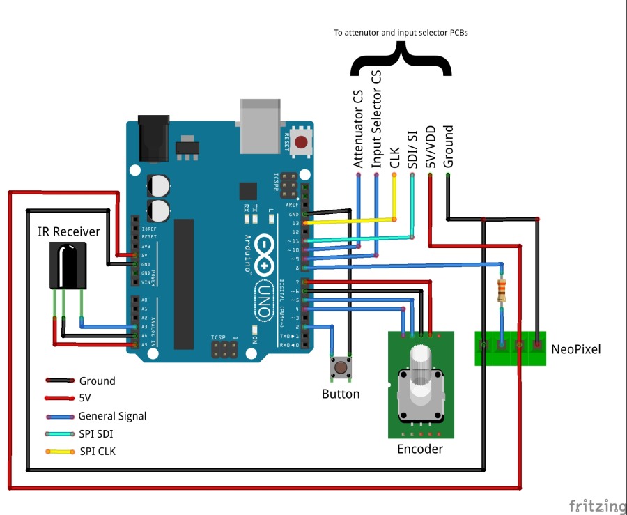
for more quick check, would you let me know how to connect the encoder?
In you diagram, there are 4 lines from encoder. My one have 5 pin. up-side pin are 3. low-side pin are 2.
would you let me know or attache more detail picture??
Thanks you.
Hi Maxw,
As I told you before by email, now I'm building up your passive preamp as an relay R2R volume controller in my preamp.
As you guess, last night i tried to upload the code into arduino and connect the passive preamp PCB, but noting happen. The led light well. but when I turned to encoder there are noting happen. No clicking sound from preamp board.
I thought I never tried arduino, so that tere are some mis-operation... ex/ libraries, how to install..
for more quick check, would you let me know how to connect the encoder?
In you diagram, there are 4 lines from encoder. My one have 5 pin. up-side pin are 3. low-side pin are 2.
would you let me know or attache more detail picture??
Thanks you.
I also need some help but with something else.
To rainwalk, the 2 pins are the build in switch and the other 3 ones are channel A/B and 5V common.
I'm doing this volume control (just the relays for volume) and I had to call the "wire" library to control the MCPxxxxx but I'm using I2C protocol.
To Maxw, need a little help with the resistor for the relays can you help ( pleaseee ) ?
Ric
Please help maxw...
I can't get my head around your volume relays resistors, I have looked online lots of r2r ladder calculators and none gives me the same values that you have in your bom.
From what I can see yours is a 10k attenuator (am I wrong ?) every time I try one of the online calculator I get different values.
Can you give me a hand please...
And when I look the code, (of course I'm really beginner of arduino) some strange lines in there. your diagram and pin number of the code looks different.
and would you alos let me know what pins should connected of the board header pin?
SI, SCK, CS on board mean that SI=SDI, SCK=CLK, CS=CS, right?
and would you alos let me know what pins should connected of the board header pin?
SI, SCK, CS on board mean that SI=SDI, SCK=CLK, CS=CS, right?
What arduino are you using?
Have you checked the pinout ?
Are you using the same type of relays (latching )?
Hi RS232,
Thans for your asking. Unfortunately, I'm real beginner of Arduino so that I don't understand what you said, checked the pinout.
But I've check the Maxw's code and wired the pin as as my guess. The connect diagram seemed different with code.
Here is some of Maxw's code
// SPI library
#include "SPI.h"
// Arduino pin 9 & 10 = Input selector & Relay attenuator
// Arduino pin 11 = SDI
// Arduino pin 13 = CLK
// Relay attenuator stuff
const int AttenuatorCSPin = 10;
byte currentAttenuatorLevel = 30;
bool muteEnabled = false;
byte lastAttenuatorLevel;
/ Encoder stuff
const int encoder0GroundPin = 6;
const int encoder0PowerPin = 7;
int encoder0PinA = 5;
int encoder0PinB = 4;
int encoder0Pos = 0;
int encoder0PinALast = HIGH;
int n = LOW;
float encoderIncrement = 2;
would you let me know right connection method based on the code? for
Passive preamp board, Encoder (different from Maxw's one), IR board etc.
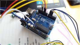
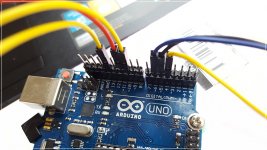
I use Arduino Uno board and other parts are same with Maxw's one.
Relay also same.
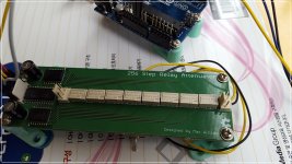
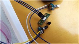
Here is my stuffs pictures for your reference. I test two different encoder but it's same... no music but relay clicking noise as like machine gun....
Attachments
visit the amb forum and search on lcduinoand delta1. max used that system and even some of my code too, iirc.
Nope. The ICs I use are SPI and the AMB devices use I2C I think.
Wow, quite a few questions.
So you got the encoder working, you can hear the attenuator changing (yes, it's loud), but you get no sound, correct? Are you using an input selector? Can you just connect the attenuator only and skip anything else in the signal chain?
Yes it's a 10K attenuator and the resistor values are not the exact values. Both the eijndhoven and amb calculators will give the same values for a 10K attenuator and you can see in my BoM that my values are close enough but not exact. You will find that getting exact values for all resistors from a single supplier is really hard if you want metal film resistors.
Yes, you are right, some pins were inconsistent. I've fixed it here:
https://github.com/FutureSharks/preamp-passive
Was there another inconsistency?
As you guess, last night i tried to upload the code into arduino and connect the passive preamp PCB, but noting happen. The led light well. but when I turned to encoder there are noting happen. No clicking sound from preamp board.
Finally I upload code to my arduino uno. when I turned on the passive preamp, it's sould like machine gun.
So you got the encoder working, you can hear the attenuator changing (yes, it's loud), but you get no sound, correct? Are you using an input selector? Can you just connect the attenuator only and skip anything else in the signal chain?
If you are using I2C then you must be using a different IC. What is the part number? Are you sure you can just drop another part in place of the MCP23S17?I had to call the "wire" library to control the MCPxxxxx but I'm using I2C protocol.
To Maxw, need a little help with the resistor for the relays can you help ( pleaseee ) ?
Please help maxw...
I can't get my head around your volume relays resistors, I have looked online lots of r2r ladder calculators and none gives me the same values that you have in your bom. From what I can see yours is a 10k attenuator (am I wrong ?)
Yes it's a 10K attenuator and the resistor values are not the exact values. Both the eijndhoven and amb calculators will give the same values for a 10K attenuator and you can see in my BoM that my values are close enough but not exact. You will find that getting exact values for all resistors from a single supplier is really hard if you want metal film resistors.
And when I look the code, (of course I'm really beginner of arduino) some strange lines in there. your diagram and pin number of the code looks different.
Hi RS232,
Thans for your asking. Unfortunately, I'm real beginner of Arduino so that I don't understand what you said, checked the pinout.
But I've check the Maxw's code and wired the pin as as my guess. The connect diagram seemed different with code.
Yes, you are right, some pins were inconsistent. I've fixed it here:
https://github.com/FutureSharks/preamp-passive
Was there another inconsistency?
Yes that is correct. Unfortunately pin naming is not exactly consistent between manufacturers.and would you alos let me know what pins should connected of the board header pin?
SI, SCK, CS on board mean that SI=SDI, SCK=CLK, CS=CS, right?
Hi Maxw
Thanks and I will try with new code.
How about encoder? I use different encoder. How should I connect into ardoino's pins?
From your pics it looks like you have encoders with a button. So there should be 2 connectors on one side of the encoder for the button and 3 on the other side connected to the encoder (A/+5V/B)
My connection diagram looks different because my encoder has 4 connectors.
If you want to copy my approach of powering the encoder from a Arduino pin then connect A/B to pins 4/5 (doesn't matter which way) and connect +5V to pin 7.
If the relays click while you rotate the encoder then it's connected correctly. If you don't hear music then perhaps you have a different problem.
- Status
- This old topic is closed. If you want to reopen this topic, contact a moderator using the "Report Post" button.
- Home
- Source & Line
- Analog Line Level
- Passive Preamp: Arduino based, remote control, Relay R2R, input selection