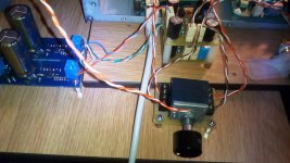
It looks like your signal/ground are swapped on either the inputs or outputs. Notice that input and output grounds are right next to each other as shown on the silkscreen.
Also notice the wires form a loop right next to the RCA jack when they split to go to shell and pin. This loop should be as small as possible to reduce coupling with the trafo and other mag sources. This is not causing your hum though it seems.
Also notice the wires form a loop right next to the RCA jack when they split to go to shell and pin. This loop should be as small as possible to reduce coupling with the trafo and other mag sources. This is not causing your hum though it seems.
Wow I can't believe I did that. Thanks for the catch. I will fix the miss wire and tighten the twist at the RCAs. I could also move the back board and stack it on top of the front board so it is a little further away from the transformer. I will also wire both boards directly off the power supply. I will not get a chance to add shielding to isolate the transformer.
I will let you know the results of the changes.
I will let you know the results of the changes.
Keantoken
Thanks for the catch, problem solved. I only had enough time to swap the wires on the output RCAs, but the hum went away. I still want to do some shielding and/or replace the wiring that comes after the switch with shielded wire.
Thanks for the catch, problem solved. I only had enough time to swap the wires on the output RCAs, but the hum went away. I still want to do some shielding and/or replace the wiring that comes after the switch with shielded wire.
If you need a buffer, then you're on the right page.
Yes, I did check. This is a fine thing.
Also, it isn't complicated.
Yes, I did check. This is a fine thing.
Also, it isn't complicated.
'powered up a pair of boards yesterday and all went (what's that old adverb?) swimmingly well.
I have a question about the circuit though as it shows a behavior I haven't seen in any of the other 431 circuits I've built 'til now.
I'm used to seeing a sudden fall-off of current once the supply voltage falls below the load plus reg compliance voltages.
In this case however, the current tracks the Vsupply in a linear way even well below 10V/rail.
I ran the board with 12V in and V*=68Ω and while I didn't try it I assume the same thing would happen with higher Vsupp and corresponding V*.
So my question is: Did you actually determine the value of R* for Vsupply so it would have that smooth transition?
I'd like to understand and learn from your thinking and I wonder if you'd open that up a bit.
Thanks
The value of R is chosen so that with a given supply voltage it will supply enough current for the circuit and shunt regulators, but not too much, with an acceptable margin. If the supply voltage drops below 10V, the shunt regulators will reduce current as much as they can to keep it up. But they can't draw negative current so it just shoots to zero. Zener diodes have the same basic behavior.
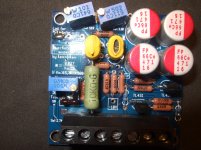
This is an amazing buffer... simple, cheap, promise for pure sound.
Attachments
Last edited:
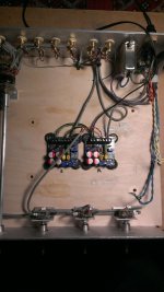
I received my boards and components in lightning speed and began to throw them together yesterday.
I yanked out my tube preamp from it's chassis and screwed in the boards and began to trim them.
In my haste and ignorance I didn't think to provide a ground to the boards. Of course I couldn't get anywhere with them. I stared at the buffer boards for awhile trying to figure out where I had screwed up too. It didn't occur to me until quite a bit later what I had done wrong. Like I said; ignorance. 😱
This weekend I'll ground them to something and give it another shot.
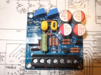
Attachments
OK, I'm stumped.
I used 68R resistors on the * marked locations as I have a 12VDC, LPS that I want to use for this. In order to get +/- 10VDC at the test points on the board I have to lower the input voltage from the LPS to 11.5VDC.
I'm using a SOLA / HEVI-DUTY SLS-12-068T power supply.
Using R5, I can get 5VDC at the test point with input shorted.
Removing the short from the input and adjusting the DC trim pot I can zero out the voltage on the input.
However, after all of this I still measure between .068VDC to .073VDC on the output. Both boards are like this.
I couldn't figure out the board grounding requirements, and initially powered the board up without one. Today I connected a ground lead from the board to the LPS chassis ground and then to AC ground. Nothing changed.
I was grounded while handling and soldering the transistors.
Any ideas on what I have done wrong????
Thank you
Last edited:
I looked up the power supply your using and it looks like it only provide positive 12 VDC. The boards need positive and negative DC to power them.
Haha!!! Whatta dope I am!
Thank you for pointing out what should have been glaringly obvious BRN!!!
Thank you for pointing out what should have been glaringly obvious BRN!!!
Got my boards put together. I followed the trimming procedure, which worked ok on one board, but not the other.
The power supply is 12v, and the on-board regulator resistors are 68R
I can't get the DC trim pot to zero volts on the input. It stays at 1.4V regardless of the trimmer setting.
One of the TL 431 regulators gets pretty hot quickly when power is applied.
I installed the second board in a mono system, and it seems to be working fine, and does not get hot.
Any suggestions where to start looking?
Thanks,
Lacro
I would list the voltages at each transistor and TL431 pin. Is it possible your power supply is the wrong configuration? The board needs +-12V with 0V being ground.
I would list the voltages at each transistor and TL431 pin. Is it possible your power supply is the wrong configuration? The board needs +-12V with 0V being ground.
Thanks for the suggestions. The power supply is the correct configuration (+-12V with 0V being ground) I checked the voltages at the TL431's. On the good board the regs are both 10V, on the bad board one is 10V, and the other is 6.6V
Which pins should I use to check voltage at the transistors (E,B,C)
The only thing I think that may be possible I did wrong was swapping the leads from the PS, V- with grd. during the first connection to the PS. I don't think I did that, but it's possible or maybe a static discharge from me, as I don't have myself grounded continuously, just touch a ground every 10 minutes or so. Any more suggestions appreciated.
Thanks,
lacro
Put one probe on ground and then just touch each pin with the other probe. Either the TL431 is dead, or something is shorting across it and lowering the voltage.The lytics would probably protect the Kuartlotron from swapped power, but I don't know how the TL431 reacts.
Ok, I swapped both TL431 regs, and the 68R resistor that gets hot from the good board to bad board. No change, but the regs/resistor from the bad board work fine on the good board, so It looks like the TL431's are ok, but one reg still gets hot as does the resistor even though they have been replaced.
I checked multiple times with a jewelers eye loupe for any possible shorts, top and bottom, but nothing.
The voltages at the transistors are all over the place, and are different than the good board.
The voltages for the BC560:
The one closest to the 1k resistor:
1(collector)= negative .21v
2(Base)=0.16v
3 (Emitter)= 0.75v
The one closest to 56R resistor:
1=.75v
2=8.5v
3=9v
The voltages for the BC550:
The one closest to the 1k resistor:
1=8.5v
2=0.75v
3=0.16v
The one closest to 56R resistor:
1=10v
2=9v
3=8v
When I check the voltage at the open unused +10v, and -10v holes, I get 10v on the +10v hole, and 4v on the -10v hole.
- Home
- Source & Line
- Analog Line Level
- The Kuartlotron - keantoken's simple error-correction superbuffer