Should you put a pot or other attenuator of the typical kOhm values before your amp and connected via an interconnect, THEN you may get lower noise/hum by putting a buffer after the attenuator/pot.
Otherwise, there is no need for a buffer in that situation.
Another situation where a buffer may be in order is if you want to drive multiple amps or things like crossovers from a passive pot or attenuator and you do not want the effects of the paralleled interconnect cables and amp input Z to combine. In which case you could use a buffer.
Buffers merely provide a gain of ~1 with a high Z in and a low Z out. Aka "isolation" and/or the ability to give a high current/low Z output (which is sometimes a benefit).
_-_-
Hi everyone, my motherboard seems to have died. Red CPU light is stuck on, and bios seems to be working, but it doesn't even POST. So that may help explain my absence, if anyone missed me.
Hello everyone
Being very satisfied with my Kuartlotron with Sulzer regulator type I was wondering if the regulator Nazar would be an excellent choice by incorporating it directly on the PCB.
🙂
It seems this circuit needs to be overloaded just once in it`s lifetime.. it has a built in self destruct tendencies 😀
Last edited:
The 10u cap could discharge through VT1 base, is that what you mean? Easily fixed with a diode.
I'm hesitant to make the PCB too elaborate, after all will any PSU ever be considered good enough?
I'm hesitant to make the PCB too elaborate, after all will any PSU ever be considered good enough?
It's an idea I want to try my Kuartlotron but I do not think that will bring here the better.
For information I made a Kuartlotron for a friend with XREG by RJM Audio matched to +/- 10V and the results to the audio are as good with my regulator Borbely - Sulzer.
http://phonoclone.com/diy-xreg.html
For information I made a Kuartlotron for a friend with XREG by RJM Audio matched to +/- 10V and the results to the audio are as good with my regulator Borbely - Sulzer.
http://phonoclone.com/diy-xreg.html
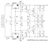
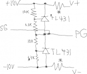
After the lytics, it is all the same as the schematic. I would have made the schematic by now but my computer died. It's pretty much the simplest possible TL431 shunt reg though, it would be easy to trace out. Look at the build info:
http://www.diyaudio.com/forums/anal...tion-superbuffer-post4834519.html#post4834519
If you don't want to use the shuntregs you can jumper the * resistors and just not add the TL431/3.3k/10k parts.
http://www.diyaudio.com/forums/anal...tion-superbuffer-post4834519.html#post4834519
If you don't want to use the shuntregs you can jumper the * resistors and just not add the TL431/3.3k/10k parts.
OK, Please post when you're up and running again.
The board is great the way it is but my project is complicated enough that I need to see exactly what's there. Experience tells me not to assume I'm seeing what you're describing, and thinking I figured it out by probing the board assumes I haven't missed anything. . . . and that's a stretch ! : )
Thanks K.
The 10u cap could discharge through VT1 base, is that what you mean? Easily fixed with a diode.
Here is a supposedly improved version of the Nazar that I'm working on a board for.
Attachments
You don't sound very excited about it. There's buckets of regulator designs out there, so why this one specifically? It looks like an okay design to me, if you want lower noise and higher PSRR ath the expense of output impedance, just curious what are the requirements?
You don't sound very excited about it. There's buckets of regulator designs out there, so why this one specifically? It looks like an okay design to me, if you want lower noise and higher PSRR ath the expense of output impedance, just curious what are the requirements?
Not sure what you mean by "not sounding very excited about it". I wouldn't waste my time laying out a board for it if it wasn't any good.
I'm no expert on the circuit. Some people over in the Pass F5 headphone amplifier thread mentioned that they built it and liked it with that particular amplifier.
That's it...nothing more nothing less.
You can read about it here.
S-Audio Systems - PSU for High end audio without electrolytic capacitors
Not sure what you mean by the circuit having a high output impedance. The article states .1-.2 ohms.
Nevermind then. This page goes into the rationale behind the Nazar regulator:
S-Audio Systems - "???????????? ??????", ????????
I say it has higher impedance because it has higher output impedance than the LM317 that's part of it. That tells us little about how it will sound though. If I were to hazard a guess it would be similar to the Kmultiplier since the output circuitry is similar.
Last edited:
Sorry about that.
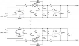
In the spirit halloween, not to disappoint, I've gone the extra mile to bring you an extra frightening schematic. Let them not say I wasn't in season.
OOOOOOOOOhhhhhhhh pretty sKerRrryyyyyyy
 y y y y
I showed my wife (who knows a resistor from an axial polystyrene capacitor) and asked what she thought of it. She said "Well, it looks kind of like a prehistoric cave painting." When I laughed she added, "Well, . . they knew about those things way back then." What could I say? It's worth framing 😀
Not sure what you mean by the circuit having a high output impedance. The article states .1-.2 ohms.
Well, I can't imagine how the output impedance can be .1 or .2 (which is also high and higher than 317 datasheet) if there is a 2.7R resistor in series after the regulator output.
Now, if you put that resistor BEFORE the regulator and between two caps, that could be very effective to lower noise.
It is actually a shunt regulator. The 2.7R sets the bias current, so the chipreg is really a CCS.
- Home
- Source & Line
- Analog Line Level
- The Kuartlotron - keantoken's simple error-correction superbuffer