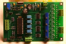
OK, this board is going to press, I can't see how I can make it any better with what I know right now.
Received some parts a few days ago that allowed me to actually test some perceived needed changes:
1) changed Vadj from single turn to multi-turn, and reference voltage is now very solid at 4.999~5.000 volts.
2) changed half of Vref voltage divider for each PIC from a fixed resistor to a multi-turn pot. This pot will allow me to set max ADC count to exactly the maximum resistance I want from the shunt LDR in a given LDR pair configuration. That will give me maximum ADC counts available within the useful range at the low current (high LDR resistance) end of the range.
3) changed the resistor driving the mosfet gates from 1 meg to 3 meg, and control is greatly improved, with much less change in LDR resistance when the mosfet is fed a correction pulse. Thus smaller pulses for finer control.
One remaining change: The current limiting resistor for the series LDR can be much greater than 150 ohms, because the series LDR will never be asked to operate at 40 ohms. I will have to find the appropriate value as the target resistor values become known, but probably will be in the range of 150 ohms for the LDR which should mean several hundred ohms in series with the LED to limit current. Again, this is in aid of ensuring the maximum number of ADC steps are available for control in the useful zone by increasing the available count at the high current (low LDR resistance) end of the range.
Moved IR control chip off the board; it was silly to divide the circuitry for that function between two locations. It'll all fit on one board together with the necessary regulator for the motor.
Now have the software running smoothly, controlling two separate LDRs simultaneously. It's obvious that the LDRs are not consistent because when the mosfets are matched delivering exactly the same current to two LDR devices, the resistance of the LDR is considerably different between devices. This is not new information, but it's interesting for me to see two devices running simultaneously with exactly the same drive current showing such different resistances on the output side.
Time to build the new board and modify the code for the new chips, and see four devices running simultaneously, responding to a single input. Once that's done, it'll be time to start writing the code to first determine the correction required for each device, then figure out how to code that correction into the drive algorithms.
Attachments
Last edited:
Excellent thinking on the multi-turn pots. And everything else seems to be maturing nicely. It'll be interesting to see what happens next.
I am retired Air Force. During Viet Nam, I was a pilot. Afterwards, I became an air traffic control officer and part-time pilot and managed ATC facilities. Later, I commanded communications and computer systems organizations (because in the Air Force, comm, computer, and ATC are combined together). Am now 66 and in my dotage. My intentions, so far as they go, is to stay above ground for as long as I can, and play with electronics and my toy airplane. 🙂
Coool! What did you fly during Viet Nam? I remember guys I knew talking about how they freaked out when they first arrived at Bien Hoa and realized that there were two three-mile-long (or whatever they were) runways that were paved with brass shell casings, and laughed (or maybe grimaced would be more accurate) at the idiots who would say things like, "Wow. Who's been shootin-off all these rounds?".
I have always been in love with aviation and aerospace. I had an uncle who flew P-47s in WWII, and another uncle (his brother) who was a brilliant self-taught engineer at McDonnell Douglas from before it was McDonnell in the 1930s until the late 1970s. I worked at their McDonnell Aircraft division, straight out of Purdue EE school, in the Guidance and Control department, from late 1980 until ealy 1984, when I resigned to start a software company. I got onto the F/A-18 project as we were completing Ship #3, in November of 1980. I remember hearing about the ceremony for the 5000th F-4 Phantom, although I never worked on that program. I did do some cool stuff for the F-15, though. (I also learned that it was pretty-much impossible to win an argument with our test pilots.)
Here's a cool story I remember: The uncle who flew P-47s had his plane go down on Dec 23rd, 1944, during The Battle of the Bulge (unable to switch from takeoff tank to main tank). He hit the stabilizer on his way out and was rendered unconscious. He regained consciousness while freefalling and pulled his ripcord. He said that the instant his canopy popped his feet touched the ground! Talk about just plain lucky. I should have gone to Vegas with him, I guess.
Dotage is such a funny word, in that context.
Cheers,
Tom
Last edited:
This project has hit what appears to be an insurmountable brick wall.
The problem is the combination of a) the sensitive logarithmic current response of the LDR requiring very fine adjustment steps at higher resistance values and b) the resolution limitations caused by the combination of limited internal math capability of the PICs together with the relatively coarse 10-bit (linear) resolution of the PIC's internal ADCs. At the low end below 200 ohms I can control LDR resistance to within a tenth of an ohm. However, at the upper end around 10K ohms, resolution is down to several hundred ohms between steps which is nowhere near close enough.
Need to think this through, perhaps take a different approach to the problem. But the specific approach I've been following here probably isn't going to work without considerable modification.
Going to take the rest of the summer off and go flying . . .
This project has hit what appears to be an insurmountable brick wall.
The problem is the combination of a) the sensitive logarithmic current response of the LDR requiring very fine adjustment steps at higher resistance values and b) the resolution limitations caused by the combination of limited internal math capability of the PICs together with the relatively coarse 10-bit (linear) resolution of the PIC's internal ADCs.
Easy to control linear voltage to logarithmic current converter:
An externally hosted image should be here but it was not working when we last tested it.
Easy to control linear voltage to logarithmic current converter:
Interesting circuit. I had not been aware of the LM1971, and it does look as though it might handle the range of currents required to control the LDR.
The problem with my circuit is not in the control of the LDR -- control of the current passing through the mosfet is infinitely variable with no steps; however, the ADC which reads the mosfet and guides it to a specific resistance is limited to 10 bits resolution. Further, the math done by the chip will only work with whole integers, so rounding errors in some places can be very serious.
Since the output of the 1971 is in defined steps, it may be possible to program a PIC to select a compensated output for a given level based upon previous measurements and without the need for feedback. I'll definitely look at that, thank you for pointing out the possibility.
I have been looking all over the internet, trying to figure out what are "optimal" potentiometer values for this application.
I think I've been heading in the wrong direction -- trying to build a potentiometer with resistance values that deliver matching impedances to the source and the load at all rotation points. This results in LDR resistance values as high as 60K for the shunt at 1db attenuation.
I'm beginning to suspect that the best values here are close to a simple mechanical potentiometer, with the top half resistance and the bottom half resistance, when added together, equaling the value of the pot and the value of the pot is (approximately) equal to the input impedance.
I gather that output impedance is at a maximum when the pot is at midpoint and the upper and lower resistances are equal. This results in an output impedance which is 1/4 the value of the pot.
So, for a 10K pot, output impendance will always be below 2.5K; is this low enough? Should the pot resistance curves be tweaked so that the upper and lower resistances are still equal but somewhat lower in value? Like, for a 10K pot, change the curve so that the two values are 3K+3K at midpoint instead of 5K+5K?
If the maximum LDR resistance I have to deal with is around 7K or less at all times, this job gets a lot, lot easier.
Any input welcome . . .
Hi
I simulate a mechanical pot in my design. Total resistance of shunt+series remains constant at 40k. This gives a nearly constant load to the source which is important for my DAC.
At the output I have a buffer, the Salas DCB1. The combination sounds really great. In theory the DCB1 has e very high impedance, but in practice it's quite sensitive to the output impedance before as it's a high capacitive load. But it sounds great. As I can do automatic calibration, I could try other impedances but I've done other things lately. I prefer the basic pot function, called KISS.
If you are "simulating" a mechanical potentiometer with a 15A taper, you can separate the analysis into two equations of resistance vs travel. Also, you can use Excel to calculate the effect of the parallel resistance of the load when coming up with the final set of equations.
Don't lose sight of the fact that for low listening levels you need less precision than high listening levels.
Don't lose sight of the fact that for low listening levels you need less precision than high listening levels.
Don't think in practical terms that it matters that the load varies a bit....as to drift from app 20K to 10K during different volume settings.. as most equipment has a rather low output impedance..
It could also be possible to make a combination of fxed resistors and LDRS to get a practical acceptable solution...
It could also be possible to make a combination of fxed resistors and LDRS to get a practical acceptable solution...
If you require a constant input impedance/resistance and a constant output impedance/resistance, then a two part, shunt & series resistances, cannot provide this.
A T attenuator is one way to get there. This T requires three accurately chosen resistances for each attenuation level.
There are probably other ways to maintain this constant input/output impedance, but I suspect all require more than two resistances.
A T attenuator is one way to get there. This T requires three accurately chosen resistances for each attenuation level.
There are probably other ways to maintain this constant input/output impedance, but I suspect all require more than two resistances.
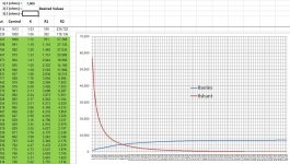
Someone posted the ladder attenuator schematic with resistor values as shown in attachment one. It has a fixed 10K input impedance and, it appears, an output impedance that is suitable to drive a 10K load.
I found the formulas used to compute the resistor values for this ladder, and did a spreadsheet. Attachment two is the resulting graph for a constant 7K input impedance and constant output impedance.
Quesstion is: Is this approach the way to go in designing an LDR volume control, or should I simply do a conventional pot where the total resistance of the top and bottom halves of the pot always equal some desired value, say, 10K?
Any thoughts?
Attachments
I don't understand what you have done.
Look at the relay schematic.
Discard all to the left of -64dB relay.
You are left with 10k in series, 10k as load and 6r31 as shunt resistor.
This is a T resistor network with 10k input impedance and 10k output impedance.
Now do the same for any single relay. It too presents 10k for both input impedance and output impedance.
I cannot correlate the T resistors with what you are showing on your graph.
Last edited:
I don't understand what you have done.
Look at the relay schematic.
Discard all to the left of -64dB relay.
You are left with 10k in series, 10k as load and 6r31 as shunt resistor.
This is a T resistor network with 10k input impedance and 10k output impedance.
Now do the same for any single relay. It too presents 10k for both input impedance and output impedance.
I cannot correlate the T resistors with what you are showing on your graph.
The trailing 10K (load) resistor in the T you describe is the 10K input impedance value of the load amplifier. Thus, the T is completed by the load amplifier.
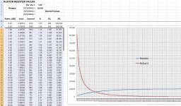
I should have changed the spreadsheet to match the 10K of the original ladder design before posting it. Look at this version, with Z adjusted to 10K.
My attenuator does not go to -63dB because it is limited by the 40 ohm minimum value of the LDR. Using this design, I can only get into the 40~50 db range without paralleling LDR devices.
Look at the 1dB rung of the ladder schematic, and the 8dB rung. The resistor values are exactly the same as my spreadsheet (rows 9 & 23) and graph. The formulas I used are the same as this (apparently) well-respected attenuator design, and the curves I show are the curves created by that design.
At this point with hardware rebuilt with some improvements included, I can now focus on the software -- which includes deciding upon which resistor values and attenuation curve to apply to both the series and shunt resistors (which are the same electrical design as the ladder attenuator shown earlier).
The main advantage of using a PIC to control the LDRs is that the PIC can control each LDR as separate devices with different resistance curves between series and shunt values. Thus, the curves shown in the attached spreadsheet are (theoretically) quite possible using LDRs.
My question is, is it worth the extra effort to design around these curves as opposed to simply emulating a mechanical potentiometer where the two resistive values always total a fixed value?
Attachments
If the 10k is the Rin of the next stage then that receiver stage does not see the 10k as it's Rs.
The receiver sees the remainder of the T without the third reisistor. The attenuator is not constant output impedance.
The receiver sees the remainder of the T without the third reisistor. The attenuator is not constant output impedance.
If the 10k is the Rin of the next stage then that receiver stage does not see the 10k as it's Rs.
The receiver sees the remainder of the T without the third reisistor. The attenuator is not constant output impedance.
Well, you know, you are just reminding me (as though I needed reminding!) that my expertise is in the digital and DC realm, not audio. I can 'shape' the resistance curves of two LDRs to any appropriate values using a PIC, but I don't know which curves would be most useful. I have tried several times in this thread to ask for help in identifying what those curves should look like, but the extent of the responses seem either to address questions I didn't ask, or just tell me I don't know what I'm doing. I know I don't know what I'm doing -- that is why I'm trying to get someone knowledgeable to help me by telling me what I should be doing in the way of designing these curves!
Low source impedance pays dividends for almost every type of receiver.
A power amp likes to see a low source resistance.
If that power amp is AC coupled it does not care if there is a small variation in the source impedance. 0r0 is OK. 10r0 is OK. 50r0 is OK, 200r0 is OK. It does not need to be constant.
The transmitter likes to see a load it can drive. Anything over 10k is usually high enough to not cause problems for most transmitters, provided there is not too much capacitance inparallel with that resistive load.
It comes back to what was said way back, constant input and output impedance offer very little when driving a power amp.
Well, trying to develop a precision LDR potentiometer with voltage control of what is a current-operated device has been a red herring and a waste of time. It would have been a simpler circuit if it had been possible, but, while control was possible, precision was not. In previous attempts using voltage regulation to control the LDRs, LDR resistance was not very stable over time. With current control, however, I find that LDR resistance is very stable and can therefore be programmed with accuracy.
I’m shifting gears. I have found a voltage-to-current converter chip and a precision op-amp which, when paired, appears to resolve all the issues and does it in a very elegant way. Each chip will operate two channels which means one of each chip per audio channel will control the series and shunt resistors nicely.
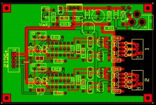
The attachment is the new board configuration.
The converter chip will deliver up to 15ma of current without a boost transistor and is internally limited at that level. The other end of the current spectrum is set by a single resistor, and if that resistor is a multi-turn trimmer, very fine control of the minimum current is practical. It appears that about 250 ohms will deliver the current required to drive an NSL32 to about 10K ohms of resistance. A 500 ohm multi-turn seems ideal for the job, and ½ watt pots are available so power considerations are met. No other support circuitry is required, just the one resistor per control channel. Full rail input to the converter will drive the converter to full current output, or 15ma out. Slightly above Gnd, say, 10mv, will be ideal to drive the converter to minimum current as set by the variable resistor. I have successfully set the LDR ohmage level to values of 5K, 10K, 20K, and 25K by varying the value of the trimmer. Very elegant solution.
The input of the converter is rather low impedance and therefore must be driven by a very capable circuit. My original mosfet & resistor voltage divider won’t do the job. I’ve found a precision op-amp which is unity-gain stable and will drive to within about 2mv of the rails given the input impedance of the converter. That means that of the 1023 counts available with the PIC’s ADC pins, approximately 1018 counts will be available to control the level of the op-amp which will control the converter. This is the best case scenario that I’ve been able to come up with so far.
Another problem that I’ve run into in trying to control the LDR is that the LDR response is very slow compared to the response of the PIC, and the lag has caused problems in software control. In this new scenario, the PIC will drive an op-amp and converter with near instantaneous response. The LDR’s lagging response will have no impact on the feedback to the PIC, so this problem will go away.
The very high input impedance of the op-amp will be a vanishingly small load on the capacitors controlled by the PIC, so very small and infrequent control adjustments will be adequate to maintain precise control voltage levels to control the op-amp inputs. If the circuit is successful, I will probably replace the .47uF metal-film caps with 1.5uF tantalums or even 15uF tantalums with matching changes in the resistor limiting PIC drive to the capacitor. This should result in fast, accurate adjustment by the PIC followed by very long stable periods when the capacitor does not require adjustment due to the high impedance of the op-amps.
In addition to the changes to the circuit resulting from the added ICs, I’ve added a facility that will allow precision testing of LDRs using the board’s circuitry simply by moving one jumper. This board therefore can be used to evaluate and select LDRs which could then be marked and sorted and selectively installed to the board – a one stop solution. The LDR test facility is always available even after all LDR positions are filled and the board is fully functional as a volume control. If fast, repeatable testing of multiple devices is desired, it would be easy to set up a rotary switch with precision resistors to program current output at multiple levels in any series desired. If this approach is followed, the mA meter could be omitted and replaced by a jumper at the J3 pins 1~2.
I’m switching to two LDRs per position – LEDs wired in series, resistors in parallel. I find that when two LDRs are wired that way, 15 milliamps results in a resistance of about 25 ohms. That means the LEDs will be loafing at 75% of full rated brightness, and the resistance will be very usable. Due to the low maximum current used, once calibrated this configuration should last for a very long time if not forever without degradation of the LED.
The power rails -- +5V and Gnd – are wired in a star-configuration with different parts of the circuit connected directly back to the regulator’s output capacitor. Various sections of the circuit should not interact and voltages should remain very stable. The regulator circuit contains a multi-turn pot for setting the voltage very accurately. In theory 5.000V is desired, and in practice, this circuit varies by .001V only.
I’m shifting gears. I have found a voltage-to-current converter chip and a precision op-amp which, when paired, appears to resolve all the issues and does it in a very elegant way. Each chip will operate two channels which means one of each chip per audio channel will control the series and shunt resistors nicely.
The attachment is the new board configuration.
The converter chip will deliver up to 15ma of current without a boost transistor and is internally limited at that level. The other end of the current spectrum is set by a single resistor, and if that resistor is a multi-turn trimmer, very fine control of the minimum current is practical. It appears that about 250 ohms will deliver the current required to drive an NSL32 to about 10K ohms of resistance. A 500 ohm multi-turn seems ideal for the job, and ½ watt pots are available so power considerations are met. No other support circuitry is required, just the one resistor per control channel. Full rail input to the converter will drive the converter to full current output, or 15ma out. Slightly above Gnd, say, 10mv, will be ideal to drive the converter to minimum current as set by the variable resistor. I have successfully set the LDR ohmage level to values of 5K, 10K, 20K, and 25K by varying the value of the trimmer. Very elegant solution.
The input of the converter is rather low impedance and therefore must be driven by a very capable circuit. My original mosfet & resistor voltage divider won’t do the job. I’ve found a precision op-amp which is unity-gain stable and will drive to within about 2mv of the rails given the input impedance of the converter. That means that of the 1023 counts available with the PIC’s ADC pins, approximately 1018 counts will be available to control the level of the op-amp which will control the converter. This is the best case scenario that I’ve been able to come up with so far.
Another problem that I’ve run into in trying to control the LDR is that the LDR response is very slow compared to the response of the PIC, and the lag has caused problems in software control. In this new scenario, the PIC will drive an op-amp and converter with near instantaneous response. The LDR’s lagging response will have no impact on the feedback to the PIC, so this problem will go away.
The very high input impedance of the op-amp will be a vanishingly small load on the capacitors controlled by the PIC, so very small and infrequent control adjustments will be adequate to maintain precise control voltage levels to control the op-amp inputs. If the circuit is successful, I will probably replace the .47uF metal-film caps with 1.5uF tantalums or even 15uF tantalums with matching changes in the resistor limiting PIC drive to the capacitor. This should result in fast, accurate adjustment by the PIC followed by very long stable periods when the capacitor does not require adjustment due to the high impedance of the op-amps.
In addition to the changes to the circuit resulting from the added ICs, I’ve added a facility that will allow precision testing of LDRs using the board’s circuitry simply by moving one jumper. This board therefore can be used to evaluate and select LDRs which could then be marked and sorted and selectively installed to the board – a one stop solution. The LDR test facility is always available even after all LDR positions are filled and the board is fully functional as a volume control. If fast, repeatable testing of multiple devices is desired, it would be easy to set up a rotary switch with precision resistors to program current output at multiple levels in any series desired. If this approach is followed, the mA meter could be omitted and replaced by a jumper at the J3 pins 1~2.
I’m switching to two LDRs per position – LEDs wired in series, resistors in parallel. I find that when two LDRs are wired that way, 15 milliamps results in a resistance of about 25 ohms. That means the LEDs will be loafing at 75% of full rated brightness, and the resistance will be very usable. Due to the low maximum current used, once calibrated this configuration should last for a very long time if not forever without degradation of the LED.
The power rails -- +5V and Gnd – are wired in a star-configuration with different parts of the circuit connected directly back to the regulator’s output capacitor. Various sections of the circuit should not interact and voltages should remain very stable. The regulator circuit contains a multi-turn pot for setting the voltage very accurately. In theory 5.000V is desired, and in practice, this circuit varies by .001V only.
Attachments
I have the chip successfully managing one LDR with fast, accurate control up to 10K ohms, looks like it might go to at least 15K, maybe 25K if anyone wants a pot with that kind of resistance range.
Have just populated the board with the other three LDRs with a view to testing out the control of four devices at once, which is the standard required for stereo. Working on the pseudo-multitasking aspects of the software now.
BTW, the board which I have shown as the latest turned out to have a fatal flaw, am talking about, and currently working with, an older version of the board. If the multi-tasking works out well, I'll build another prototype of the board.
Last edited:
- Status
- Not open for further replies.
- Home
- Source & Line
- Analog Line Level
- A precision LED/LDR-based Attenuator