The multi-tasking piece is going very well. I now have the two parts of the virtual potentiometer (R1 & R2) going in opposite directions simultaneously exactly as a pot would do (as the top half of the pot increases in resistance, the bottom half decreases) for one audio channel. Response speed is still very fast; tomorrow when I add the code to drive the third and fourth LDR devices for the second audio channel, I expect that the speed loss will be unnoticeable. This stage has gone much faster than I expected.
The multi-tasking piece is going very well. I now have the two parts of the virtual potentiometer (R1 & R2) going in opposite directions simultaneously exactly as a pot would do (as the top half of the pot increases in resistance, the bottom half decreases) for one audio channel. Response speed is still very fast; tomorrow when I add the code to drive the third and fourth LDR devices for the second audio channel, I expect that the speed loss will be unnoticeable. This stage has gone much faster than I expected.
I now have all four LDR channels working. Speed is reduced a little bit, I guess it was inevitable. Speed is limited by the tradeoff between precision adjusting of LDR current levels and rapid adjusting of current levels. In order to get good accuracy in LDR resistance setting, it is necessary to throttle the rate of adjustment change so that the PIC can keep tight control. Speeding up the rate of change also means that each step of adjustment is going to be bigger. The bigger the adjustment, the less granularity is available.
Implemented Balance control in software, works well and required just 40 bytes of compiled code. The board is now real "stereo" -- with one pot controlling volume to both audio channels, and the other pot controlling the balance between the channels.
Will need a fully working system to determine how much of a "dead zone" to leave in the middle of the Balance pot, and where to set the speed-of-change for best "feel."
Will need a fully working system to determine how much of a "dead zone" to leave in the middle of the Balance pot, and where to set the speed-of-change for best "feel."
Here's a model for the Fairchild H11F1M Analog OptocouplerBack in 2008, I put the resistance and current values for it (from the datasheet) into my general LDR model that was originally used for the VTL5C2 device. But you might have to add the time constants, etc. And of course the model doesn't take into account any of the variations for temperature, or variations between different devices, etc. But I guess it's still pretty useful.
.subckt VCRES 1 2 4 5
RIN 4 6 1
VT 6 5 0
GRES 1 2 VALUE = {V(1,2)/(165+(0.07229* (V(4,5)^(-1.5))))}
.ends
Seems to work OK, within about a percent from 1mA to 16mA. The factors were calculated with Equalize.
Here's a model for the Fairchild H11F1M Analog Optocoupler
.subckt VCRES 1 2 4 5
RIN 4 6 1
VT 6 5 0
GRES 1 2 VALUE = {V(1,2)/(165+(0.07229* (V(4,5)^(-1.5))))}
.ends
Seems to work OK, within about a percent from 1mA to 16mA. The factors were calculated with Equalize.
I looked at the Fairchild devices, but I'm back to working with the Silonex devices because I think they'll work better. Have you actually tested any of the Fairchil devices to determine how close the reality is to the published specs?
I also went looking and found a couple of discussions online that commented on the unusually high distorition that the Fairchild devices caused at anything above a very low level signal. The Fairchild data sheet talks about 'zero distortion' which sounds unlikely to me, and that coupled with real-world experimenters giving up on them in audio applications because of excessive distortion has put me off of them.
I recently did a quick check of twenty or so LDRs I had on hand for the purpose of learning what kind of current range I would need to plan on to accomodate practically any LDR in my design. I found that the required currents at 50 ohms and 10,000 ohms varied widely between devices. The attached list is my result (after I discarded one LDR that was totally off the chart). I'm assuming since the two ends I'm concerned with were so varied in current, all the resistances between those two point will be equally diverse between devices.
Attachments

Last edited:
You can take any device, take the measurements and then figure the parameters for the spice equation. The important thing is that they are all are going to follow the a general equation like R(I) = K1 + K2*(X^-1.5). What I had suggested way back in this thread is that instead of buying a 20 or 40 LDRs you just find the parameters which fit.
I'm sure not a spice guy, so the formula you cite I cannot follow. Could you tell me in words how spice would deal with a device where 50 ohms could require anything between 4.5ma or 12.5ma?
You've got a constant (K1) and a slope (K2) -- let's say you are feeding a line amp with the output of the LDR attenuator -- you use a voltage divider to equalize the K1's, and adjust the slope by modifying the gain for the K2's.
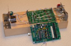
 I made major changes to the board in the picture in post 158 -- I completely reworked the control circuitry between the PIC and the buffer op-amp. The board looks a total mess (see attached picture), but I now have very solid control of the LDR at any resistance up to 50K.
A new board design based on all of the changes incorporated in the kludged board is 95% complete. All of the major components of the firmware are written with the exception of the code that will convert the values of a linear pot into the required logarithmic curve of a standard volume control. I've only used about 250 bytes of 2048 available, so space is not going to be a problem.
My target "standard" pot using the LDRs as the resistive sections will be a 52dB attenuation 10K pot using either six or eight devices, TBD. If you assume a 10K or higher output load on the "pot", the series resistance stays above 100 ohms in all cases, which means only a single LDR will be required for the series component. The shunt resistance will be series diodes, parallel resistors pair of LDRs with a minimum resistance of 25 ohms. This provides the 52dB attenuation.
Next step is to optimize two key resistor values, and then I'll start writing the firmware code to convert a linear control pot into a logarithmic response audio control.
I started out to design a simple board that used LDRs in a volume control, but it turned out that the precision I wanted required technical complexity. The result is going to be a fairly technically complex hardware and software solution that hopefully will yield great operational simplicity -- an LDR volume control with tight log response and close tracking between channels.
Last edited:
It's turning out rather nice! I've been following the thread since its start, looking forward to the first production test run!
Wow what a nice development!!
Very nice development!!
Love to see how you get around all the obstacles!!
What I like is the fun you have in going on in the direction you really want! Hope you will be able to bring it back to more simplicity once you have reached your goal!
The other aspect I like is the perfect teamwork in this thread. No shouting or empty discussions. Just building together.
Wel done, hope you get to a final product we can DIY (even the not so clever ones like me / technically speaking that is 😉
Regards
Peter
Well, depending on how I look at it, it's great progress or just progress-of-sorts.
I'm looking at my 4.5 digit meter, and it's reading 9,651 ohms at minimum volume pot attenuation (and that's good because it's the shunt resistor I'm looking at).
The down side is that I'm operating the PIC outside of the Microchip specification. And it has to be this particular model chip to work, another (earlier) version of the chip with similar specifications doesn't work at all. But I think that this version is good -- every sample I've tried works OK.
Right now the control is extremely sensitive (even though I'm using a 10-turn linear pot) because I haven't entered the linear-log conversion algorithms into software yet. So at one end of the pot, minimal travel changes resistance a lot and at the other end there's very little change for a given rotation of the control. The rotation of the pot is so small compared to the change in resistance that I'm actually using 10-bit ADC feedback through the computer to measure the relationship of pot movement to change in resistance.
Let's see if I can calculate the drive voltage change to the constant current chip that results in about 1K resistance change in the LDR at 10K ohms. The calculator result is this:
2.9325513196480938416422287390029e-5
I don't even know how to read that, but whatever it is, it's vanishingly small.
I know I could get tighter control by using an op-amp in the CC chip feedback, but the circuit is complex enough as it is, my goal has always been to keep it simple; adding a precision op-amp (x4) to the board would make it downright ridiculous.
I'm sure that at the moment the physical layout of the circuit is introducing jitter-producing noise, and a clean rework of the board would reduce that quite a bit. I'm almost to the point that I have enough confidence in the circuit that a completely new board is justified, but not yet. If I can find a single current sense resistor value that will work with every LDR I throw at it, I'll replace the output trim pots with fixed value metal-films. That would do quite a bit to settle resistance drift, I think. I've already decided to reduce the LDR count from eight to six devices for the two audio channels.
Have now completed enough hardware testing so I feel OK about fully populating the board with LDRs.
Did a very basic pre-screen of each device requiring (almost every device passes this test):
a) 50 ohms or less at 12ma
b) 10K ohms or more at .005ma
That guarantees each device is capable of delivering the resistance required for the board to operate over a resistance range of 25 ohms to 10K ohms. Beyond that, no prescreening necessary, since the PIC will learn the characteristic of each LDR pair and control accordingly. The .005ma achievability is based on the PIC's resolution capability (I'm forcing operation outside the Microchip specification, but it works), the resolution of the resistor/mosfet voltage divider network, and the constant-current chip's sense resistor value. To build a pot with a total resistance exceeding 10K ohms (a 25K pot for a tube amp, for example) the LDRs will need to be hand-picked with tighter standards. However, due to the precipitous drop-off of current above 10K ohms, the difference in drive between a 10K pot and a 25K pot is minimal.
The attached photo is of the control board and the bed-of-nails test board which houses the precision .1% resistors and connections required to allow the PIC to read the LDR and "learn" what control output results in what LDR resistance.
The next step is to enable the code to control all four channels of LDRs simultaneously with each two channels of LDRs operating as the two resistors comprising an adjustable potentiometer.
Total current consumption at worst-case scenario (maximum attenuation) should be about 30~35 milliamps, and the TO-220 LM317 will be loafing.
Attachments
I'm working on an active speaker project right now. Speaker is 2 way, and I may add a sub in the future.
Your project looks appealing for the volume control.
Thanks for the effort.
Are you going to share the pic code, and latest schematic at some point?
Randy
Your project looks appealing for the volume control.
Thanks for the effort.
Are you going to share the pic code, and latest schematic at some point?
Randy
Are you going to share the pic code, and latest schematic at some point?
Randy
I haven't decided, but in reality there doesn't seem to be any point in doing so -- in order to use it, you'd have to have a working knowledge of the programming language, have a PIC programming capability on top of the regular board-building capability (including soldering SMT ICs).
Further, when the board is built, you'd have to calibrate the board and that would require understanding and using the math involved in the formulas, and also building the calibration hardware jig with the added resistors and connections to allow the calibration process to go forward.
In short, there are so many disparate skills involved that I don't think it's going to be a good candidate for DIYing for most people for a one-time project, though I concede that there may be exceptions.
I'm already thinking ahead to "Son of PLDR" which would use the same principles but sacrifice some of the precision so that it could be built by most people. It would still require programming the chip, however, which probably most people would not want to be involved with.
At this point, I've got 70+ components on the 2.5"x4" board, and I think the board is pretty much ironed-out and in close to final form.
This board is pretty much a final configuration.
Two areas of the hardware might change:
1) The values of R22~R25 may change once I’ve got the board up and testing. I know the calculated values but real world factors may yet intervene. I’m moving away from the trimmers that I was using previously.
2) For each of the two channels, I have planned for two LDRs for the series leg of the pot and two more for the shunt leg; however, when calculating resistor values for a 10K pot driving a 10K (or higher) amplifier load, the lowest series resistor value required for .5dB attenuation (the least attenuation I’ve planned for) is just under 300 ohms, and that minimum value is even higher for higher ‘pot’ values like, say, 25K ohms. Thus, the series leg should be adequately served by a single LDR rather than the two in series/parallel that I’ve planned with the shunt leg. If I’m right, I’ll just jumper the power leads for one of the LDR positions for each series pair and change the layout for the next board.
The op-amp and voltage-to-current converter chips I’ve selected for this project are the OPA2342 and the AD8277. I like them because they are unity gain stable, rail-to-rail, high precision, and require only four external resistors (R22~25) to correctly drive two complete channels (four legs of LDRs).
I switched C8~C11 from metal film to tantalum to get a larger value. Adjusting the RC network driving the mosfet gates will give a better combination of quick response and a more stable voltage to drive the op-amp inut.
For the heck of it, I put ground planes on both sides of the circuit card. Hopefully there’s no hidden gotcha lurking when I do that because the science of ground planes is above my pay grade. The circuitry is operating at DC levels, so I’m assuming that extra stray capacitance is not going to bother the circuit. If anyone sees this and knows I’m doing something wrong, I’d love to hear about it.
Attachments

wapo54001,
The board layout looks really very good, to me, now. Excellent job!
Sorry but I have just a couple more bothersome questions and suggestions. ;-)
Is there some reason for not also putting ground planes in the LDR area? I would at least want to run the "current in" and "current out" traces for the LEDs as close to each other as possible, so there is no enclosed loop area between them to act as a receiving (or transmitting) antenna. Actually, I'd probably want to just flood the LED area with the "current out" (green?) copper, so it would (also) cover the area on the opposite side of the pcb under the red "current in" traces, giving very low enclosed loop area, in that region at least.
That same flood-fill could also basically eliminate the effects of sharing the single "current out" trace by currents from multiple LEDs, which would probably be a good idea, so that the distributed voltages induced along the traces (which would basically appear back at every LED cathode) by current from one LED, flowing through the trace impedance, wouldn't affect another LED, and using more of a plane would also minimize the effect of each LED's own current on its own downstream voltage, which overall would present a more-constant "ground" voltage to the more-negative end of each LED.
The input and output impedances worry me a little, with only 10k max LDR resistance. With a realistic "average" setup, i.e. with "average" amplifier input resistance (maybe 10k) and source output resistance (maybe 50 Ohms, or even 0.01 Ohm), what would the plots of the attenuator's input and output impedances look like, or what would be the max and min of each?
Are you running the 50 Ohms to 10k Ohms LDR profiles linearly (vs pot travel), with about a 5k/5k intersection at the volume pot's midpoint? Or do you have them as log or log-related functions?
What kind of options have you got, for the resistance profiles, and what have you tried, and how has it affected the maxes and mins of the Zin and Zout?
Cheers,
Tom
Tom, your post comes under the heading of "I'll just spend a few minutes writing this here, and let's you -- Wapo -- spend the next month working this stuff out. . ." 🙂
Well, even if I wanted to, I don't have the electronic training to deal with all that, I am a rank amateur. I'll tell you what I think and why I think some things are OK as is.
First, ground planes in the LDR area -- I thought if there was any current flowing through it, I'd just keep it clear of the audio path. Don't see a reason to include the LDR area.
Actually, given the DC-nature of my circuit, other than the PIC area and power connections (which travel through multiple capacitors), there should be no noise at all. Where signal goes high or low as driven by the PIC, the circuit typically holds that condition for many milliseconds, and there should be no high frequency switching hash. Also, control signals coming out of the PIC immediately go through a 1 megohm resistor into a 2+uF capacitor which changes charge very slowly; there just isn't a lot of opportunity for noise.
Second, regarding current flow from the LEDs: Maximum current flow in the worst-case scenario (both channels volume at minimum but not muted) would be !0~20ma total with 5~10ma drawn from each channel, and it would be steady-state. I made the power tracks .040, which is the recommended size to carry several amperes so I can't get too excited about 20ma.
Currently, both top and bottom planes are connected to ground; I could make the top plane +5 and the bottom plane ground . . .
With regard to the input/output impedances, I have created a spreadsheet that allows me to enter the pot value and the amplifier load value and the spreadsheet gives me R1 and R2 values at 1/2 dB steps of attenuation for the given pot. I can increase the value of the pot to any value and get the resulting resistor values at 1/2dB steps. If I need to get fancier and change the R1 and R2 values in such a way that they do not always equal the theoretical value of the pot, then I'll consider it, but you'll have to explain to me what the objective is, and show me the formulas for making the calculations. There also is a practical limit to this that relates to the increasing difficulty of controlling the LDR at higher resistances.
Re the pot being linear or log -- I answered that above, I am planning to use a linear pot to control the circuit, but percentage linear travel of the pot will result in equal percentage change in dB -- a log curve.
As for calculating the Zin and Zout, I haven't done anything in that area. Again, give me the formulas, and I will try to integrate it into my spreadsheet. I'll also need to know what I'm trying to accomplish -- what is a desirable Zin and Zout objective.
this applies to almost every Member of the Forum................... I am a rank amateur. ................
There are very few professional Audio Members on this Forum, maybe a thousand or so, but that is just a guess, because even fewer declare the information in their profiles.
Don't use "amateur" as an excuse for avoiding work and/or learning.
- Status
- Not open for further replies.
- Home
- Source & Line
- Analog Line Level
- A precision LED/LDR-based Attenuator