Wait : for atmega16 you must program a second fusebit : Disable Jtag !Today I connected boards and turned power on. Well, I have some problems.
First of all, I reversed A and K on LCD backlight, so it must be corrected (my post #55 in this thread).
Then, pushbutton for on/off can't turn off until backlight is on.
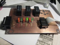
Third, and most important, is that only three of six relays for volume work. I checked resistor, transistor and relay chains, all six of them are working properly, I just don't get enough voltage from pins to open transistor.
I programmed chip with internal 8MHz clock, but I have delay between steps for volume aprox. 1 second, and for input select aprox. 2 seconds. Is it OK?
Tommorow I'll reprogramm chip and, if it still doesn't work properly, I have to try with another mega16. I used all precautions against static electricity, I just don't belive that I damaged it.
And like magic everithing will be working !
The rest off relay are on JTAG lines of MCU and to work as I/O port the JTAG must be disable .
Then : the soft is write in the way as after power on you cannot power off again but after minutes !
It is like this : a lot of users of my project ask for this feature in case someone stay with the finger on on/off button or remote and the principal power souce is smps !
You know what can be happening if a smps experience in 1 minute 10 cycle of on/off !!
Everything is ok in soft : that are features , not bugs ( most of them asked by the users on Romanian forum ).
If you want ,tell me here ,what changes in soft makes you happy and I will deliver (but remember to tell me what version of firmware you use !) , wherever there are instant on/off time or quicker changing ( the delays ) .
Regards.
---------------------------------------------
About the remote : the easy way is to use a universal remote and to scan till your controller do a power on/off command and that is the code .
Or to find an RC5 Phillips IR remote command that work by trying .
Last edited:
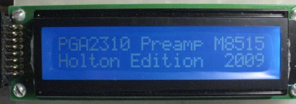
Now it works perfectly
I already wrote that I do not want to hurry, I read all 41 pages of Romanian forum, I knew what i have to do. So, how I did it wrong?
I called my friend Milan to help me about programming. He is expert, but he works with PIC controllers. We downloaded Bascom and realized that it's too complex, then downloaded AVR ISP, which is simple for work. We adjusted everything like it should be, including JTAG disabled and internal clock of 8MHz. It was done in just a few minutes, no problems at all.
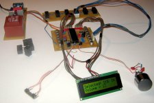
What happened? We didn't know that each step must be programmed separately, so we just put program in EEPROM, and nothing else. Today we saw that internal clock is 1MHz and JTAG enabled. We reprogrammed controller and now it works like Swiss clock.
Tomorrow I'll post some pictures.
Danzup, don't change anything in software. It's perfect!
Thanks a lot.
I already wrote that I do not want to hurry, I read all 41 pages of Romanian forum, I knew what i have to do. So, how I did it wrong?
I called my friend Milan to help me about programming. He is expert, but he works with PIC controllers. We downloaded Bascom and realized that it's too complex, then downloaded AVR ISP, which is simple for work. We adjusted everything like it should be, including JTAG disabled and internal clock of 8MHz. It was done in just a few minutes, no problems at all.
What happened? We didn't know that each step must be programmed separately, so we just put program in EEPROM, and nothing else. Today we saw that internal clock is 1MHz and JTAG enabled. We reprogrammed controller and now it works like Swiss clock.
Tomorrow I'll post some pictures.
Danzup, don't change anything in software. It's perfect!
Thanks a lot.
What does it mean -each step? What steps? Explain pls. a bit more, I'm just about to face the same issuesWe didn't know that each step must be programmed separately, so we just put program in EEPROM, and nothing else.
")
@ Vikt0r
Short answer:
Open AVR-ISP, load Danzup's software and adjust fuses and lockbits, then open Device, use Program for EEPROM, Fuses and Lockbits separately.
Then use verify and that's it. Good luck.
Long answer: tomorrow if I find my friend Milan.
------
We are not going shoulder by shoulder, it looks more like a turtle and a rabbit.
I'm going slow, you're going fast.
Short answer:
Open AVR-ISP, load Danzup's software and adjust fuses and lockbits, then open Device, use Program for EEPROM, Fuses and Lockbits separately.
Then use verify and that's it. Good luck
.Long answer: tomorrow if I find my friend Milan.
------
We are not going shoulder by shoulder, it looks more like a turtle and a rabbit.
I'm going slow, you're going fast
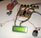
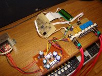
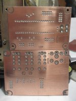
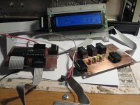
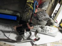
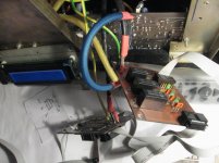
.I promised some pictures. Here they are.
What I didn't finish is input board (you can imagine it when you see some relays), because I still don't know how my preamp will look like. Options are one enclosue or two separated (one for audio and one for supply/control). The same reason is for front plate.
Connectors and cables are from old TV's, DVD's and PC's. I'll change them in final version.
Attachments
-
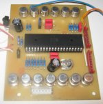 Control board.jpg146.4 KB · Views: 1,925
 -
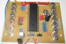 Control board 2.jpg124.9 KB · Views: 1,875
 -
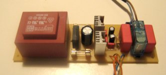
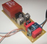 Power supply.jpg112.9 KB · Views: 1,805
 -
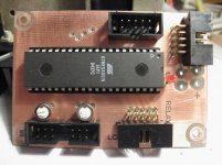
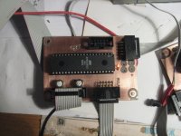
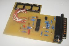 Programmer.jpg125.7 KB · Views: 635
 -
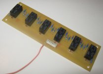 Volume.jpg145.6 KB · Views: 1,708
 -
 Power supply 2.jpg130.8 KB · Views: 1,757
 -
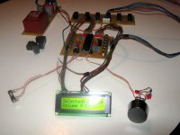 It works!.jpg157.4 KB · Views: 761
 -
 It still works.jpg129.5 KB · Views: 790
 -
 It works like Swiss clock.jpg172.8 KB · Views: 866
Well, looking at your pictures I remeber the tale about the turtle and the rabbit, where the rabbit was so proud of his speed, that did not notice the hard-working turtle and it reached the finish line
You work is GREAT, especially I like your PSU, which ashames mine (made on a perfboard) - I wouldn't even show up. Oh, and my programmer...well, it looks MUCH simpler However, I did not try it yet
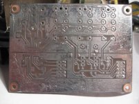
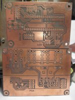
Would you please show some shots of your solder sides..?
P.S. Your project makes me crying - as I have nowhere to source those wonderful rotary encoders...
You work is GREAT, especially I like your PSU, which ashames mine (made on a perfboard) - I wouldn't even show up.
Oh, and my programmer...well, it looks MUCH simpler However, I did not try it yet Would you please show some shots of your solder sides..?
P.S. Your project makes me crying - as I have nowhere to source those wonderful rotary encoders...
Last edited:
@ Vikt0r
1. Don't belive in fairy tales. You are too old for them. Life learned us that rabbit IS faster than turtle.
2. Actually, my PSU is a copy of alex.mm PCB from post #1 of this thread. I just added trafo and replaced some components to fit on one half of Euro format (160x50).
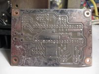
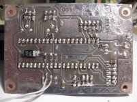
3. Hmmm... I tried to hide solder side of my PCB's. Usually, when I develop foto sensitive laquer, I use permanent marker and straighten all lines and pads. Then I have to wait 24h before etching. I wasn't patient, I wanted results fast and made a mistake. So I had to solder all copper. Looks ugly, but works. The other reason is that I didn't wash flux yet. Now it's too late for pictures, I'll send them tomorrow, maybe in the evening, because I have a lot of obligations.
4. Don't cry. In Serbia you can nowhere buy any rotary encoder. This one is from defective (late, dead) amplified DVD player. I got it from (guess who?) my friend Milan. It would be much better if I could find encoder with pushbutton and there connect select command. It means that you can select input and adjust volume with only one button, by pressing and rotating it.
5. It's really late now, I must go to bed. Greetings.
1. Don't belive in fairy tales. You are too old for them. Life learned us that rabbit IS faster than turtle.
2. Actually, my PSU is a copy of alex.mm PCB from post #1 of this thread. I just added trafo and replaced some components to fit on one half of Euro format (160x50).
3. Hmmm... I tried to hide solder side of my PCB's. Usually, when I develop foto sensitive laquer, I use permanent marker and straighten all lines and pads. Then I have to wait 24h before etching. I wasn't patient, I wanted results fast and made a mistake. So I had to solder all copper. Looks ugly, but works. The other reason is that I didn't wash flux yet. Now it's too late for pictures, I'll send them tomorrow, maybe in the evening, because I have a lot of obligations.
4. Don't cry. In Serbia you can nowhere buy any rotary encoder. This one is from defective (late, dead) amplified DVD player. I got it from (guess who?) my friend Milan. It would be much better if I could find encoder with pushbutton and there connect select command. It means that you can select input and adjust volume with only one button, by pressing and rotating it.
5. It's really late now, I must go to bed. Greetings.
The encoder :
Expresie căutată: ED16112O // Elemente şi piese electronice componente - TME – Electronic Components
or this with push switch on shaft :PIHER|CI-11CO-V1Y22-HF4CF|ENCODER INCREMENTAL | Farnell România
Expresie căutată: ED16112O // Elemente şi piese electronice componente - TME – Electronic Components
or this with push switch on shaft :PIHER|CI-11CO-V1Y22-HF4CF|ENCODER INCREMENTAL | Farnell România
The encoder :
Expresie căutată: ED16112O // Elemente şi piese electronice componente - TME – Electronic Components
or this with push switch on shaft :PIHER|CI-11CO-V1Y22-HF4CF|ENCODER INCREMENTAL | Farnell România
That's great, but nothing in Ukraine. It's a damn simple thing, which... nobody sells/imports, tired searching everywhere. Buying some 1-3 from abroad - the cost will exceed any reasonable limit...The only idea I have - to adopt a stepper motor from a floppy drive to work as an encoder. This can be done with a little comparator schematic, and it gives a solid feeling response - steps are very precise and soft.
Made it! It's working now (however I did not test the volume control function as finished 2AM at night...). During debugging found one mistake on the relay PCB, one solderbridge at the controller board and figured out that my lovely white-on-blue LCD is dead This significantly spoiled my feeling of victory, but at the end - it works (so far with an ugly green one).
Danzup - THANKS!
As soon as you have copyrighted your software - I'm asking for your permission to modify it later on up to my needs (I'm going to change names of inputs, probably add one or two more - an S/PDIF and a USB one.
Otherwise - ITS PERFECT, man! Thanks for making my old dream come true, Danzup!
This significantly spoiled my feeling of victory, but at the end - it works (so far with an ugly green one).Danzup - THANKS!
As soon as you have copyrighted your software - I'm asking for your permission to modify it later on up to my needs (I'm going to change names of inputs, probably add one or two more - an S/PDIF and a USB one.
Otherwise - ITS PERFECT, man! Thanks for making my old dream come true, Danzup!
Congratulation !Made it! It's working now (however I did not test the volume control function as finished 2AM at night...). During debugging found one mistake on the relay PCB, one solderbridge at the controller board and figured out that my lovely white-on-blue LCD is dead
Danzup - THANKS!
As soon as you have copyrighted your software - I'm asking for your permission to modify it later on up to my needs (I'm going to change names of inputs, probably add one or two more - an S/PDIF and a USB one.
Otherwise - ITS PERFECT, man! Thanks for making my old dream come true, Danzup!
Everyone can use the software under GNU licence , so you can modify wherever you want !
Good luck and more pics ...!
Good luck and more pics ...!
Okay, I owe this...
Here is how my gear looks like, so far, before it get's into enclosure.Attachments
PCB renewal
I remade my version of PGA2310 Volume Control PCB. I decided to make separated PCBs - one PCB for digital part and for analog the other one. All parts from old PCB were unsoldered and soldered again on brand new PCBs. My PGA2310 successfully pass 4th solder/unsolder cycle and now all work perfect!
I changed source code a little bit: on/off feature was removed and some screens were modified.
And some photoes...
Attachments
-
 IMG_7265.jpg257.3 KB · Views: 1,269
 -
 IMG_7262.jpg789.4 KB · Views: 1,453
 -
 IMG_7260.jpg732.9 KB · Views: 1,757
 -
 IMG_7266.jpg246.8 KB · Views: 1,178
 -
 IMG_7273.jpg289.6 KB · Views: 406
 -
 IMG_7274.jpg220.5 KB · Views: 513
 -
 IMG_7411.JPG948.7 KB · Views: 549
 -
 IMG_7410.jpg230.9 KB · Views: 698
 -
 IMG_7408.jpg359.3 KB · Views: 726
3 more photoes
So cool !
I like it !
Also the passive tone controller will arrive in the next week or so ( maybe in future weekend ..) on this thread .....
3 more photoes
I just noticed the KT315's
Didn't meet them for ages - Home
- Source & Line
- Analog Line Level
- Yet another Volume controlers and source selections