Hi
2 Vikt0r
If its not too late I can post here my PCB version under PGA2310 danzup project. But I dont use any specific soft for PCB tracing, I draw all my PCBs in CorelDrawX3.
If its ok - just ask an I publish it here today in the evening.
Preved, Pryanick! 🙂
Sure, I'm interested. But does your PCB feature the SMD atmega?
Dan,
You forgot about shunt operation mode, also supported by pcb design.
Can you consider to update the GB post title 🙂
You forgot about shunt operation mode, also supported by pcb design.
Can you consider to update the GB post title 🙂
Preved, Pryanick! 🙂
Sure, I'm interested. But does your PCB feature the SMD atmega?
You can use the gerbers and files for controller only pcb (the pcb with atmega16-8au smd and LCD) from project nr.3 , from here :
:: vicol audio :: R-2R volume controller ::
and then I will rewrite the soft and post a schematics for connecting this controller (the pcb with atmega and LCD) with a pcb with pga2310 and relay for input selection ( made by you or another from forum ).
Do you want this ?
Because first must be cut the rest of the pcb from pannel ..... to remain only the control board !
🙂
Last edited:
Oh, guys - thanks, appreciate - but no need to.
Hopefully during the weekend I'll develop something by myself.
Anyway, I'm planning to place the controller and the PGA+relays to different
boards in order to minimize the affect of the digital stage to the analog. It's
going to be "one more design", let's see if I can make it.
Will come back soon.
Hopefully during the weekend I'll develop something by myself.
Anyway, I'm planning to place the controller and the PGA+relays to different
boards in order to minimize the affect of the digital stage to the analog. It's
going to be "one more design", let's see if I can make it.
Will come back soon.
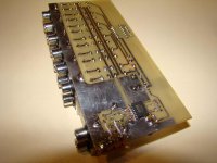
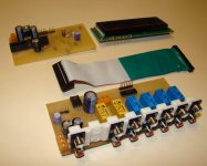
Finished designing, etching and drilling the analogue stage PCB. Took me about 4 hours all in all. Photos will follow soon. The PCB fits the input/output jacks, relays, a ULN2003A driver, the PGA 2310 and a 7805 voltage regulator for it's digital part alone. Analogue and digital grounds are split apart and connected via a ferrite bead inductor. Signal path is minimized.
Let's say it's an attempt to get a step closer to a "proper implementation" of this chip. If anyone's interested - I'll share the design as well - it's already possible to use it combined with the microcontroller (which is recommended to be kept as far away as possible from the signal path).
Let's say it's an attempt to get a step closer to a "proper implementation" of this chip. If anyone's interested - I'll share the design as well - it's already possible to use it combined with the microcontroller (which is recommended to be kept as far away as possible from the signal path).
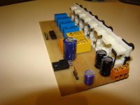
So here is how it looks like.
The PGA is bypassed with small SMD ceramic caps close to the leads. The ferrite bead is also an SMD inductor. The analog PSU bypass caps are Rubycon ZLG, the digital part bypassed with a Sanyo OSCON.
The PGA is bypassed with small SMD ceramic caps close to the leads. The ferrite bead is also an SMD inductor. The analog PSU bypass caps are Rubycon ZLG, the digital part bypassed with a Sanyo OSCON.
Attachments

So here is how it looks like.
The PGA is bypassed with small SMD ceramic caps close to the leads. The ferrite bead is also an SMD inductor. The analog PSU bypass caps are Rubycon ZLG, the digital part bypassed with a Sanyo OSCON.
Exceptional !!! I like`t !
Congratulation for your PCB !
Bravo!
Exellent job, Vikt0r. It's hard to belive that your work is done in just four hours. I work a month and a half and I didn't finish yet 😕. Congratulations 🙂.
Exellent job, Vikt0r. It's hard to belive that your work is done in just four hours. I work a month and a half and I didn't finish yet 😕. Congratulations 🙂.
Okay, maybe that was five hours... 🙂 Thanks guys for such positive feedback, catch some more then... 🙂
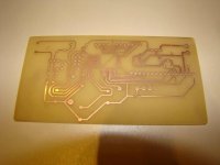
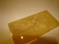
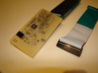
This is the MCU board for PLCC atmega. This one took me some more, needed to spend half a day digging the datasheets. Now only the PSU PCB will remain.
Come back with updates soon.
This is the MCU board for PLCC atmega. This one took me some more, needed to spend half a day digging the datasheets. Now only the PSU PCB will remain.
Come back with updates soon.
Attachments
Danzup,
as far as I understand, you've used BASCOM-AVR for creating and compiling the code. What did you use for flashing the chip itself, I mean - which schematic and software? I am planning to build the simplest-ever-possible type of ISP programmer - appreciate your suggestions.
as far as I understand, you've used BASCOM-AVR for creating and compiling the code. What did you use for flashing the chip itself, I mean - which schematic and software? I am planning to build the simplest-ever-possible type of ISP programmer - appreciate your suggestions.
AVR prommer
Vikt0r,
as for me I soldered very simple "USBasp - USB programmer for Atmel AVR controllers".
Original link:
fischl.de - USBasp - USB programmer for Atmel AVR controllers
BASCOM-AVR supports USBasp since version 1.11.9.6😉
Vikt0r,
as for me I soldered very simple "USBasp - USB programmer for Atmel AVR controllers".
Original link:
fischl.de - USBasp - USB programmer for Atmel AVR controllers
BASCOM-AVR supports USBasp since version 1.11.9.6😉
Thanks, Pryanick, but...
No problems to solder it together, but it still requires programming the Atmega8. Since I don't have anything yet - I need a simpler programmer at first. Maybe that would make sense to solder a USB one later.
No problems to solder it together, but it still requires programming the Atmega8. Since I don't have anything yet - I need a simpler programmer at first. Maybe that would make sense to solder a USB one later.
Yes .
It is STK200/300 programmer header for parallel port .
In Bascom this must be set in the programmer adapter type .
Bascom AVR compiler you will find to download for free .
On the schematics I forgot to draw the signals for programming so you must use the following pins of Atmel :
Reset , Miso , Mosi , SCk , 5Vcc , Gnd .
Do not forgot to program only the fusebit : Internal RC 8Mhz oscillator.
Wow,
thanks guys! One of these will definitely do for me, found an ALS244 already. Interesting founding that some different (and incompatible!) pinouts for the ISP exist. The Atmel appnote recommends a 6 pin header, while at many designs a 10-pin one can be found.Which one is more standard? Another question - would this all SW accessing the LPT port work under Win7? Has anyone tested it?
Oh... the WIP, if anyone's interested 🙂 Very draft yet, just finished soldering, didn't even wash the board.
Attachments

Last edited:
It works...almost
Today I connected boards and turned power on. Well, I have some problems.
First of all, I reversed A and K on LCD backlight, so it must be corrected (my post #55 in this thread).
Then, pushbutton for on/off can't turn off until backlight is on.
Third, and most important, is that only three of six relays for volume work. I checked resistor, transistor and relay chains, all six of them are working properly, I just don't get enough voltage from pins to open transistor.
I programmed chip with internal 8MHz clock, but I have delay between steps for volume aprox. 1 second, and for input select aprox. 2 seconds. Is it OK?
Tommorow I'll reprogramm chip and, if it still doesn't work properly, I have to try with another mega16. I used all precautions against static electricity, I just don't belive that I damaged it.
That looks like a s/w bug, we need to ask danzup to correct it.Then, pushbutton for on/off can't turn off until backlight is on.
What transistors did you use? Are you sure they're darlingtons?I just don't get enough voltage from pins to open transistor.
What voltage do you use to power Atmega?
I'm not danzup, but I don't think it's okay, and I don't think it has anything to do with 8Mhz. Do you have a scope? Can you take a look at the unstable relay's transistor driver, what's going on there? And what's on atmega the pins...I programmed chip with internal 8MHz clock, but I have delay between steps for volume aprox. 1 second, and for input select aprox. 2 seconds. Is it OK?
Don't worry too much, these chips do tolerate a lot.Tommorow I'll reprogramm chip and, if it still doesn't work properly, I have to try with another mega16. I used all precautions against static electricity, I just don't belive that I damaged it.
One more thing: did you try the IR remote control? Does it work for you?
- Home
- Source & Line
- Analog Line Level
- Yet another Volume controlers and source selections