I believe
R4 is a very high compared with R2
Therefore, feedback amount via R4 is consided very small
Approximately, R4 and R6 is just a dc voltage divider.
Actually, the voltage gain must be decided by the relation
between the loop gain and the fraction of R3 and P1 . . .
If R2 is increased, it would be another story
Then, the voltage gain could be predicted as R4/R2.
R6?
In this case, R6 takes a role for the frequency bandwidth decision of the closed loop
Happy New Year
Babowana said:I believe
R4 is a very high compared with R2
Therefore, feedback amount via R4 is consided very small
Approximately, R4 and R6 is just a dc voltage divider.
Actually, the voltage gain must be decided by the relation
between the loop gain and the fraction of R3 and P1 . . .
If R2 is increased, it would be another story
Then, the voltage gain could be predicted as R4/R2.
R6?
In this case, R6 takes a role for the frequency bandwidth decision of the closed loop
Happy New Year
babo........please confirm my mails
Babo, Isn't there a current relationship here? Where, considering no current into the gate, and excluding R6, you would have the same current through R2 and R4 with 0 Volts at the gate node(0 voltage/current summing point?). Where all your input voltage across R2 would dictate the current. And that current across the R4 would dictate the amount of feedback/gain???
However, we have an R6??? With an AC effect also. So, some of the current from the output, is lost to ground. And, actually, some of the input voltage and current flows to GND through R6 also???
I beleive the PLH had a similar circumstance???
I'm not sure of the AC implications of R3 and RP1 in john's current circuit. And, I thought them, in the interest of ZEN philosophy, uneeded... For everyone's info, my simulation of the Circuit in post #271, using no R3 or RP1 and a 20K R2 says: Using a 2V p-p input, I see 1.35V p-p at the gate node(in phase with the input signal), and 18.56V p-p at the output(Naturally 180 degree's out of phase)... That is a gain of 9.28??? Obviously the R6 is messing up anyone's typical idea of what the gain is in my circuit... And John's also... It is not just the contribution of the R3 and RP1? But, what is it?
Ohh, I forgot, My sim is not exactly like #271,,, I used 8 ohm loads and a 40V supply 😀
I thought that for R3 and P1 to create a feedback loop they had to be located on the fet gate side of R1. I reversed this and placed R1 on the gate side of the divider; does this delete the feedback loop on the power fets?
John🙂
John🙂
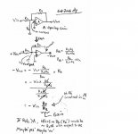
Let’s have a look only with R2, R6 and R4.
And assume the buffer gate as a virtual ground.
We thevenize R2 and R6 with Vin.
Then Rth=R2//R6, Vth=Vin x R6/(R2+R6)
So, Vout=Vin x R6/(R2+R6) x R4/ (R2//R6)
Conclusion: Vout/Vin=R4/R2, leaving R6 canceled off.
(Refer to Malvino’s Section 40-something, linear op-amp,
I don't remember the section number well . . .)
Whatever R6 value is, the gain is expressed as R4/R2.
I.e. prediction of the gain is 442K/221= 2000 ???
This is not feasible, IMHO
The measurement will show much lower than this.
The gain must be earned by the combination of
the open loop gain and R3&P1 feedback
🙂
I'm already lost in references in last few pages of thread........but-if your talk is about circ in post #271,then only OL is worth considering;
I can't see any feedback path anywhere........at least not effective and contributive ;
if we presume that gate resistors are 20K ,and feedback resistor is 442K........through 442K we have positive feedback?
I'm gonna sleep.......I'm already stoooooooooopid enoughjkl;'
edit
stoooopid input buffer is non inverting
there is just stooopid ZM with even more than usual 4 eyes.
stooopid amp
sez lil' foxie, turnin' own back from grape tree 😉
edit edit
I found carp's scmtc 158 pages back.......increase input resistor or-even better put 221 to gate and put in his place something as 10K..................decrease 442 K to 47K and then see what ya get.........susy,mebbe with few aditional problems ,maybe not.......sorry-I can't cover so much threads ,I'm not Papa 😉
in any way
I guess this is the Pass Labs Forum 😀 Unlike others, at times, We always have Positive Feedback here 😀 😀 😀
Zen Mod said:your talk is about circ in post #271,
My reference is post#227 on page(23).
BTW I got your 21 mails, each of wich includes 2MB size attachment, total more than 40MB . . . But, I could not open the attachments. I will re-try to open them tonight.
🙂
And,
Choky, he he . . . I agree with you
442k is too big compared with 20K
This time I'm referring to #271, Flg's . . .
🙂
Choky, he he . . . I agree with you
442k is too big compared with 20K
This time I'm referring to #271, Flg's . . .
🙂
Babowana said:
My reference is post#227 on page(23).
BTW I got your 21 mails, each of wich includes 2MB size attachment, total more than 40MB . . . But, I could not open the attachments. I will re-try to open them tonight.
🙂
just sent you explanation mail ( I killed ya with 40 megs,and then I giv ya expl 😉 )........
if this is (attached) circ ,then all my "edit" mumbo jumbo few post above is regarding that......
Attachments
Babowana said:And,
Choky, he he . . . I agree with you
442k is too big compared with 20K
This time I'm referring to #271, Flg's . . .
🙂
ya can call me BabothenBabothenflgthenCarp

Zen Mod said:ya can call me BabothenBabothenflgthenCarp
I am a babo
You are a baboer than babo
So, Papa doesn't like both of us, I guess 😀 😀 😀
No others resembling us
Shut up and go to bed and good dream
Babowana said:
I am a babo
You are a baboer than babo
So, Papa doesn't like both of us, I guess 😀 😀 😀
No others like us
Shut up and go to bed and good dream

This is the current configuration:
Btw, there must be some feedback. When I inserted a signal at the gates of the power fets, there was a slight blip on the lower tip of the output sine wave. When the signal was placed in it's normal position (before the buffer), the blip disappeared at the output.🙂
Btw, there must be some feedback. When I inserted a signal at the gates of the power fets, there was a slight blip on the lower tip of the output sine wave. When the signal was placed in it's normal position (before the buffer), the blip disappeared at the output.🙂
Attachments
John, What are you using for V+? Do you still have something like 23V at the speaker outputs? And, are you running a S.E. input to the +Input and grounding the -Input?
I think those 36 ohm R's to ground are mighty hot??? You could probably get away with something a little higher in value???
I still have't figured out the gain thing totally. Other than to say, R3 and RP1 are not effecting gain. And when I set up my circuit of post #271 without any feedback, I get an open loop gain of 20 😀 That's with a S.E. input, with the - Input GNDed and differential output.
Hi flg,
I'm now running 29 volts at the input and 25 volts out of the choke.
The 36 ohm resistors are what I have on hand at the moment. When I get back to work, I'll purchase resistors closer to 50 ohms. The 36 ohm resistors are sandwiched/clamped into my heatsink ribs and spacers--beautiful set-up. If 72 ohms were acceptable, I could always series the 36 ohm resistors. I have a whole sack full.🙂 There's plenty of room in the heatsink.
The single-ended output from the receiver is channeled through a device that supposedly adapts it to xlr/balanced mode. I don't know what it's doing internally, but I do know that its negative output is flat-lined on the o'scope. So I assume the ZV7-T amp is now single-ended.
I did connect everything to a true balanced Aphex single-ended/balanced converter and didn't care for the results. The ZV7 is accurate sounding, but lacks that wonderful warmth that I've grown so accustomed to. I'm staying with the single ended approach.
As configured, this amp exhibits excellent micro-detail. Its midrange isn't quite as full as I'd like, but the details are fascinating. It's like the amp focuses on them at partial exclusion of the music's body--perhaps it overpowers the body. I'm not saying that this is the perfect solution, but it certainly is enjoyable. And, since I'm hard of hearing in the upper frequency range, I find this to be quite a blessing.🙂
babowana, I'll try to sort out what you're trying to teach me--thanks for the drawings.
I really have had a good time with you guys, and feel tremendous appreciation for your involvement.
Many thanks,
John
I noticed in the ZV7-T schematic I posted several post back that R13a has the incorrect value; it's supposed to match R13 @ 571 ohms.
John🙂
John🙂
We should use the inverting configuration because the amp as a whole is inverting. Your feedback from the + input side is negative after the Power FET.
The trouble is, unlike the opamp configurations, that there is a DC voltage at the output that will appear at the Buffer gate through the feedback network. We need to keep that DC gate voltage at something useable. The R6 resistor can do that but it has an effect on the AC signal also. That messes with our simple understanding of the feedback network.
In the circuit I suggested, Post #271, I set up the Buffer gate voltage properly to also bias the Power FET and disposed of the C2, R1 and RP1 components. I can easily see what the gain is when working on the simulator.
- Status
- Not open for further replies.
- Home
- Amplifiers
- Pass Labs
- ZV7-T (transformer)