In the circuit I suggested, Post #271, I set up the Buffer gate voltage properly ...
I like that arrangement and will utilize it in my next project.🙂
I've been thinking about the stuff I've been reading, and a thought came to mind: isn't' the buffer combination I'm using in reality a differential pair? I think I have a differential pair driving a differential pair.
What do you guys think?
John🙂
What do you guys think?
John🙂
To have a differential pair, you ussually have to have your sources tied together so they steal each others current during operation. Generally that is a controled source of current feeding the pair. Diff pairs are in the common source amplifier configuration where the output is taken from the drain.
The input pair of transistors on your ZV7-T are common drain configuration😀 😀 😀
The input pair of transistors on your ZV7-T are common drain configuration😀 😀 😀
Hi flg,
I tried your idea of raising R2 to 10K. The body is back in the mid-range, although there is a bit of sacrifice in the extreme top-end micro-detail.
Sounds good.🙂
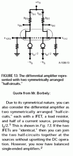
I based my premise on a recurring thought of Mr. Borbely's jfet tutorial where he depicts a pair of transistors in a similar configuration as my buffers. Just pondering...
I tried your idea of raising R2 to 10K. The body is back in the mid-range, although there is a bit of sacrifice in the extreme top-end micro-detail.
Sounds good.🙂
I based my premise on a recurring thought of Mr. Borbely's jfet tutorial where he depicts a pair of transistors in a similar configuration as my buffers. Just pondering...
Ref: post#294
Ref: post #296
Into the small equilateral triangle symbol
the buffers
the gain MOSFETs
the coils
part of resistors
part of capacitors
part of wires
part of soldering points
are all compressed, and imperceptible
The sketch simplifies and emphasizes the outer feedback section
showing left (or right) half of the ZV7-T
It looks like the negative feedback of the inverting op-amp
I think
ZV7-T is an X-differential amp having a CCS tail
but, the buffer is just a buffer which is provided mainly for
the input impedance increase, and distortion improvement
somewhat as a side effect . . .
carpenter said:Here's the piece of info that's perplexing me:
Yes, that's a diff pair. Notice the dotted line connecting the sources

N.P.'s BZLS and Aleph Preamps along with the SOZ all have this configuration. A resistor inserted at the dotted line can control differential mode gain.😀
carpenter said:
I tried your idea of raising R2 to 10K. The body is back in the mid-range, although there is a bit of sacrifice in the extreme top-end micro-detail.
Sounds good.🙂 ...
John, I don't really like the idea of the 442k feedback R. That's a really high value. Maybe a 220k for R4 and a 75k for R6 and keep the 10k R2 might help... I believe your R1 and R1a could be lowered to 100-200 ohms or so and that may help the high end too?
What happened to your gain with the addition of the 10k R2? Did you need to change the input level to compensate?
hi guys,
flg, the problem with R1, if I recall correctly, is that it was raised from 220 to 1K to prevent inductor loading oscillations (or something along those lines). I will have to re-read the ZV7 article to get Nelson's exact reason.
Yes, I did have to raise the gain at the x-over a full click (there are 6 clicks total).
I can play around with R4 and R6... I'll get back to you with the results.
Good news: My cardiologist tested me today and told me that my heart's ejection factor (the heart's ability to pump blood into the body) has increased from 25 percent to 50 percent; the average person has 65 percent.😀 😀 😀 I'm getting there!
John🙂
carpenter said:................
Good news: My cardiologist tested me today and told me that my heart's ejection factor (the heart's ability to pump blood into the body) has increased from 25 percent to 50 percent; the average person has 65 percent.😀 😀 😀 I'm getting there!
John🙂
😀
John, good to here your condition is improving😀
I took a look at N.P.'s ZV6 and ZV7 paper. There appears to be a mistake in ZV6 fig 4, where he has 221 ohm input resistors but, the text refers to them as 1k ohm, and setting the gain. He calls the gain about 12db??? I guess that's with a balanced input??? and of coarse balanced output. I think that might be about 4 in "absolute" terms. I forgot how to do that type of conversion but I beleive the gain doubling(2X) is +6db, a gain of 3 is about 10db, a gain of 10 about 20db, and a gain of 30 about 30db and so on...
The R1 + 2 in his circuit of ZV7-T (fig 8) are doing what your R2 + 2a are doing. You have however displaced them to outside the buffer... N.P. does make refrence to the gate resistor of the ZV7-R Current Source as being 1K in this circuit rather than the typ 221 ohms to prevent oscilations induced by some inductive loads He also sets the voltage at the current source drain to 5 Volts to allow a little swing when a S.E. input( -input Gnd'ed) is used. I've been using 4 Volts in my sims, maybe I should adjust that. What do you have at the drain of your Current Source???
When N.P. introduces the ZV7-T, He also adds the .5 ohm Source Resistor to the current source. At these rediculously high currents (6 Amps) That resistor has 3 Volts on it!!! I was only using .33 ohms in my sims and 4.4 Amps total... What kind of current are you running???
After reading all that... I might even suggest a lower R2, R4 and R6 value. It should improve the high frequency performance...

I took a look at N.P.'s ZV6 and ZV7 paper. There appears to be a mistake in ZV6 fig 4, where he has 221 ohm input resistors but, the text refers to them as 1k ohm, and setting the gain. He calls the gain about 12db??? I guess that's with a balanced input??? and of coarse balanced output. I think that might be about 4 in "absolute" terms. I forgot how to do that type of conversion but I beleive the gain doubling(2X) is +6db, a gain of 3 is about 10db, a gain of 10 about 20db, and a gain of 30 about 30db and so on...
The R1 + 2 in his circuit of ZV7-T (fig 8) are doing what your R2 + 2a are doing. You have however displaced them to outside the buffer... N.P. does make refrence to the gate resistor of the ZV7-R Current Source as being 1K in this circuit rather than the typ 221 ohms to prevent oscilations induced by some inductive loads
He also sets the voltage at the current source drain to 5 Volts to allow a little swing when a S.E. input( -input Gnd'ed) is used. I've been using 4 Volts in my sims, maybe I should adjust that. What do you have at the drain of your Current Source???When N.P. introduces the ZV7-T, He also adds the .5 ohm Source Resistor to the current source. At these rediculously high currents (6 Amps) That resistor has 3 Volts on it!!! I was only using .33 ohms in my sims and 4.4 Amps total... What kind of current are you running???
After reading all that... I might even suggest a lower R2, R4 and R6 value. It should improve the high frequency performance...
I told ya already-in this case (last carp's schmtc) existence of R4 and R4a is completely unnecessary,just because amount of feedback through them is minuscule....and what you have is practically open loop
my proposal is this:
R6 and 6a =100k to 147K (as now)
R2 and 2a =10K
R4 and 4a = 47K to 82K with same 25p across
maybe I'm wrong,maybe I'm not...........
or leave it as is ,remove R4s and fiddle with all sort of source degeneration (equalized ,too).........
my proposal is this:
R6 and 6a =100k to 147K (as now)
R2 and 2a =10K
R4 and 4a = 47K to 82K with same 25p across
maybe I'm wrong,maybe I'm not...........
or leave it as is ,remove R4s and fiddle with all sort of source degeneration (equalized ,too).........
Choky, I currently have R6 and R2 at your suggested values. I can change R4 but it might alter the gate voltage of the buffer. The ratio I have seems to be giving me a decent looking sine wave. I'll experiment with your idea though and get back to you.
Lee, here's the specs:
+V = 28.3V
+V at choke output = 24.2V
CCS
G = 7.13V
D = 6.2V
S = 2.97V (that would be 5.94 amps)
Gain FET
G = 9.87V
D = 24.6V
S = 6.27V
buffer FET
G = 6V
S = 10.1V
It'll be interesting to see what you think. 🙂 I ended up taking a long nap and didn't get R4 and R6 lowered to your suggested values. Tomorrow will be better.
John🙂
Hey, I'm about ready for a nap myself. I'm a couple hours later over here...
So, As long as I was lookin at N.P.'s stuff, I went and dug up an old ZV7-T sim file I had and changed it back to the way N.P. had it😀
Then I went and tried to make one that is just like your's... You may have given me the data I need to make it more accurate... Tomorrow😀 😀 😀
One thing though, I only have the 044 transistor model and I think the 044N is a little better... Maybe I can nab it from the IR web site soon???
Zen Mod has the right idea, You need to get a little more control of gain and feedback. But, then you will be up around 20 Volts on the buffer and you'll have to modify the resistors above it also. etc. etc.
That's why I like your idea of lowering all three values: R2;R4;R6.
Maybe starting R4 off at 100K? I noticed that there's a 3 to 1 ratio between R4 and R6. That would land me with 33K for R6 if R4 is 100K. I like the idea of reducing R2 because the micro-detail seems stronger.
John🙂
Maybe starting R4 off at 100K? I noticed that there's a 3 to 1 ratio between R4 and R6. That would land me with 33K for R6 if R4 is 100K. I like the idea of reducing R2 because the micro-detail seems stronger.
John🙂
You can make R4 a 100K and the gain will be similar or perhaps slightly higher than the original ZV7-T. That would be about 7.2, where the original had about 6.5.
You might consider bringing the R6 down to 100K also as the votage on the buffer would be a little high at about 18V.
At the very high end, the original ZV7-T is -3db beyond 100kHz on my sim. Without lowering those 1k gate resistors you are using you are at -3db below 30kHz...
Also, At your input you need a larger cap than your 1uF. N.P. used a 47uF. Even if you are using the amp for mids and highs, I would go with a 5-10uF.
These are all Ideas gained from playing on the simulator. I know they don't have ears, and it's only measureing in it's own perfect little way, and many would say Baa Hum Bug, but, I find it to be a great starting point most of the time
😀 😀 😀
That having been said, why are we doing this buffer thing now??? Did we need a higher input impeadance? I think we have that
carpenter said:I like the idea of reducing R2 because the micro-detail seems stronger.
John🙂
Hi John
It is good news from you that the lower R2 is the better.
By the way, I understand that the idea of this buffer was first introduced by Papa to ZV4 project, mainly to increase the input impedance, without sacrifising top frequency (or opposite way, i.e. with improving response of top frequency). if I look into the datasheet, ZVP3310's input capacitance is very low, making us possible to have high-value gate resistor. If I look at the ZV4, there is the gate resistor of 47K. This might imply that it is quite okay for us to have the gate resistor up to 47K when we use ZVP3310 as a buffer.
As far as I learn from your posts, you are not concerned about the lower input impedance at all. If so, I would try R2, R4 and R6 with the following values:
R2: 10K
R4: 47K
R6: 15K
And, If not very satisfied with, I would try linear variations applying the common reduction factor to all three.
Meanwhile, as the 1uF input cap is forming a high pass filter with the following resistors behind of it, the variation of the resistor values might affect the speed of low frequency roll-off. Therefore, I would also prepare spare film caps of 2uF, 3.3uF, 4.7uF, 7.5uF and 10uF. Just in case.
In my opinion, if the buffer helps neither for the higher input impedance nor for the top frequency improvement, the buffer might be useless addition as Flg indicates above.
Good luck 🙂
O.K. but that will bring the gain down quite a bit. I see an open loop gain of about 20-24 or so. Setting gain at about 7 (about 18db) leaves about 10db left for feedback😀 😀 😀
Hi guys,
Thanks for the suggestions; I'll experiment with them, today.
Lee, I like the buffer because it makes the music more delicate and detailed sounding; it also cleans up the sine wave (there was that little blip on the bottom trace).
I used the small input cap to keep the amp from performing unnecessary work. When I compare the sound it produces against that of the Hafler P3000 on the other channel, I hear the same frequency cutoff. It's much more refined and detailed sounding than the Hafler, and seems to play much higher frequency. Maybe it's not that it has a higher top-end, but just does its range better.
Something else:
Now this is where I get confused: a source follower can never deliver more output voltage than it's input voltage, so how does it enter into the gain equation?😕
John🙂
The Follower doesn't enter into the gain eqauation except for the few % of signal it looses(gain of slightly less than 1). In most cases it's strengthens the preveous stages ability to drive the next stage by virtue of it's low output impeadance. In the case of ZV7 and most ZENs it would be applied to, It provides a low source impedance to drive the 1200p + capacitance seen in the gate of these big FETs. Higher source impedance or high value resistors such as R2 and R4 in your ZV7, create a low pass filter function that causes the upper end to roll off. That is why N.P. used a 1k input and a 10k feedback R in ZV7. But a 1 k input R makes for low input impeadance that your preamp may have trouble driving.
In my ZV9-L, I had a 10k input and 75k feedback R. I had a rounded 10kHz squarewave output waveform. When I switched to a 5k input and 37.5k feedback (same gain, lower resisitances)the waveform looked more square. When I looked at it open loop, no resistors, with a 50 ohm signal generator, it was nice and square to beyond 100kHz! So, I'm going to try a buffer on it. With the buffer, the input R and feedback R are interacting with the 50p of the ZVP3310 gate, not 1200p of the big FET. Basically a much higer frequncy to that rolloff bis. A cleaner High frequency performance hopefully😀 😀 😀
In my ZV9-L, I had a 10k input and 75k feedback R. I had a rounded 10kHz squarewave output waveform. When I switched to a 5k input and 37.5k feedback (same gain, lower resisitances)the waveform looked more square. When I looked at it open loop, no resistors, with a 50 ohm signal generator, it was nice and square to beyond 100kHz! So, I'm going to try a buffer on it. With the buffer, the input R and feedback R are interacting with the 50p of the ZVP3310 gate, not 1200p of the big FET. Basically a much higer frequncy to that rolloff bis. A cleaner High frequency performance hopefully😀 😀 😀
- Status
- Not open for further replies.
- Home
- Amplifiers
- Pass Labs
- ZV7-T (transformer)