I notice that Relcap/"Audio-Cap" only charges $235.00 each for their 1uF caps. I should purchase them by the case.😀
carpenter said:I notice that Relcap/"Audio-Cap" only charges $235.00 each for their 1uF caps. I should purchase them by the case.😀
you mean........"instead of the case" .........

Hi, John
I have the best cap, which is "no cap"
With R2 of 221, the R4 is not working as an ac feedback.
I would remove C1, R4. And I would replace R6+RP1 with 47K.
I'm not joking . . . 😀
Regards
I have the best cap, which is "no cap"

With R2 of 221, the R4 is not working as an ac feedback.
I would remove C1, R4. And I would replace R6+RP1 with 47K.
I'm not joking . . . 😀
Regards
Babowana said:Hi, John
I have the best cap, which is "no cap"
With R2 of 221, the R4 is not working as an ac feedback.
I would remove C1, R4. And I would replace R6+RP1 with 47K.
I'm not joking . . .
Regards
nope
I tried;
that approach is just not working with carpenter

Seems to me that R4 and R6 are setting the bias voltage for the power FET. They also adjust the DC offset. Changing them results in using the old bias scheme for the original ZV7-T w/out buffer.
🙂
🙂
you mean........"instead of the case" .........
Wouldn't it be funny if the guts turned out to be standard issue found on Digi-key...😀
I have the best cap, which is "no cap"
I wonder who gave me the idea to use a cap in the first place?

carpenter said:I wonder who gave me the idea to use a cap in the first place?
If we have R4, we definitely need the dc bloking cap.
If we don't have R4, we do not need it.
Yes R4? Yes cap necessary.
No R4? No cap necessary.
Of course, you know this better than me 😉
Hi all,
I've been studying Nelson's "Return of Zen" tutorial and have gleaned a few new ideas.
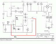
In the pic (sorry for the poor quality, my software can't resolve the pic worth beans)... ah yes, in the pic, I've drawn a red line indicating my interest in this article, which describes my current situation quite well.
I.e., I can keep my R4/R6 bias network as is and control DC, but I can also have a separate feedback circuit outside the input cap (controls cap distortion along with everything else) that has a reasonably low value that might do some good at cleaning up the amplifier. Mind you, it sounds wonderful--I just like to play and learn at the same time.
Since I think the amp sound terrible with R2 being a high value (anything over 1k), I'll just use a lower value feedback resistor in the new loop.
Comments?🙂
Attachments
Carpenter, How are ya doin Back to a constructive posting thread
I want to point out that the Zen design is using a big cap at the output, which keeps the output at no potential (Basically Gnd). the ZV9 does too. Therefor, using a feedback loop as you are suggestiing works fine on the basic Zen topology.
Your amp's bridged output, or differential, or balanced, or whatever, has positive volts on it The speaker see's the same positive voltage across it's terminals, which is basically no difference to it. But taking feedback from that point, will bring that voltage back to your input.
That is what we've been trying to work out all this time with feedback and the voltage divider bias bis
In order to do what you are thinking, you would need to add a cap in series with your feedback R. But that negates the purpose of having the cap within the feedback loop...
Nobody said all this was easy


 Back to a constructive posting thread
I want to point out that the Zen design is using a big cap at the output, which keeps the output at no potential (Basically Gnd). the ZV9 does too. Therefor, using a feedback loop as you are suggestiing works fine on the basic Zen topology.
Your amp's bridged output, or differential, or balanced, or whatever, has positive volts on it
 The speaker see's the same positive voltage across it's terminals, which is basically no difference to it. But taking feedback from that point, will bring that voltage back to your input.
That is what we've been trying to work out all this time with feedback and the voltage divider bias bis

In order to do what you are thinking, you would need to add a cap in series with your feedback R. But that negates the purpose of having the cap within the feedback loop...
Nobody said all this was easy


flg said:
Nobody said all this was easy


Yeah, but it sure is fun🙂
I have caps in the output of my electronic x-over, so it's not going to be harmed by the ZV7-T's output dc. I'm running the feedback on the outside of the input cap to the ZV7-T, so it's pure AC feedback at the buffer w/out dc.
I tried it already😀 just before supper. It works like crazy. The crazy part being that I hooked the feedback up backwards. Boy did that sucker HOWL🙄 🙄 🙄 I learned a lot about positive feedback in an instant. Not very pretty.
I discovered my mistake and rerouted the wire-clips. Presto.
In a nutshell: I ran a 1K input resistor and a 10k feedback resistor. One particular song I listen to has a bit of grain in the female voice. With feedback, the grain disappeared. Unfortunately, so did some of the sparkle.
I'm going to experiment with different amounts of feedback resistance. I'm also going to try running the amp in balanced mode.
I'll be back😉
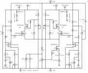
John, the object of cascoding is to maintain a constant Vds on your gain transistor. Therefore don't you want the bottom of RP4 and RP5 to connect to the sources of Q1 and 2???
I'm not sure R8 and 8A are best connected to the output, wouldn't it be better connected to the +V...
Just some ideas
I'm not sure R8 and 8A are best connected to the output, wouldn't it be better connected to the +V...
Just some ideas

 I though I was following Terry and Nelson's ideas correctly. I'll have to study more.
Thanks for the tips,flg.
John
Terry's schematic shows zener diodes in place of RP4&5. I thought it might be nice to be able to fine tune the beast. But, I'm more than happy to try the zeners.
John😀
John😀
Something that's been confusing me: does the choke load double the output AC voltage?
If it does, is the added voltage independent of the output FET? I thought R8 & 8a might need to see the actual voltage that the drain pins see in order for the gain stage to be stable.
Remember Q1 & 2 biasing resistors that I originally routed to V+? The bias floated all over the place. When I routed the resistor to the drain of the power fet everything fell into place.
John🙂
If I understand your first question... Yes, the choke"creates" a votage that ideally could be double what the circuit itself could swing. In other words. I beleive your circuit output can swing from 21V (I don't remeber exactly) down to about 9-10V. It can swing up to about 33 Volts probably. But your only putting in 23 Volts... Amazing 
Independant of the output FET??? I would say no. It will see that 33 Volts at it's drain.
I can't say much about the 3rd part there. Your V+ should be a stable point to refrence from, more so than the output node... I'm not positive I'm looking at the right Schezmo (Terry's) but I think his cascode is fed from the +70Volts???
Do you also realize you will be loosing some voltage swing by going to cascode, unless you raise your supply voltage.
I see... I'll just have to check these ideas out in my next fabrication.
Lee, today I revamp the original buffered ZV7-T, so that it's topology matches the last amp I fabricated--it utilizes the idea you gave me, direct coupling the buffer to the gain fet.
Anyway, I was just blown away at the difference in the stereo imaging with matching topologies. I'm also hearing even more extended highs. A tympani drum has the most amazing sound on my system. I never realized how many high frequency harmonics are included in a drum note.
Thank-you Lee--from the bottom of my heart.
John🙂
- Status
- Not open for further replies.
- Home
- Amplifiers
- Pass Labs
- ZV7-T (transformer)

