Yes, I beleive you are right. But, I need a resonable number of turns. And the core is not to big... Lets just pretend it's a headphone amp😀 or a PC Speaker Amp. Maybe good for an amp or 2. There is this issue of what do I do with the small prototype if it comes out like I want??? I guess I'll build a little ZV7T... I am eventually looking toward a balanced ZV9T I guess. Or something like that idea.
I want to find out if I know at all what I'm doing... DIY really accelerates that process... I'm just not doin it to fast. I'm playing with Flyback Transformer stuff trying to do what a 30lb piece of iron does??? I'm not sure I will get supprising results??? In my experience Ferrite is 30-50% the size of iron and I'm no where near that yet
I want to find out if I know at all what I'm doing... DIY really accelerates that process... I'm just not doin it to fast. I'm playing with Flyback Transformer stuff trying to do what a 30lb piece of iron does??? I'm not sure I will get supprising results??? In my experience Ferrite is 30-50% the size of iron and I'm no where near that yet
neat stuff you're playing with, flg
BTW, there's a great little iron-core transformer calculator located at:
http://student.math.hr/~sklaic/electronics/
More iron seems better for less wire; problem is the resistance can become too low.
Have fun,
John Inlow😀
BTW, there's a great little iron-core transformer calculator located at:
http://student.math.hr/~sklaic/electronics/
More iron seems better for less wire; problem is the resistance can become too low.
Have fun,
John Inlow😀
Pretty...
Why don't you take a moment to describe to me your topology? I have a general understanding of what I see, but would love to hear your take on the design. Other than the input transformer, it resembles what I want to eventually build.
Thanks for sharing,
John😀
Why don't you take a moment to describe to me your topology? I have a general understanding of what I see, but would love to hear your take on the design. Other than the input transformer, it resembles what I want to eventually build.
Thanks for sharing,
John😀
Carpenter:
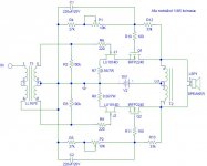
It is very simple really, it is just a differential cascode with a mosfet ontop of a jfet. It is inductively loaded so the efficiency will be close to 50%. Since there is no feedback the output impedance will be very high, just like the FirstWatt F1. Since i drive it with a very well balanced input i dont need a high impedance current source like the F1 but can instead pull the jfet source resistors directly to ground. I really like the simplicity of this one and have very high expectations on its performance, i hope i will not be disappointed!
BR,
Anders
Interesting!
I see you specify the Lundahl LL1676 for T1, how about T2? Do you have a recommendation?
Also, I see a V2, but no V1. Is something missing?
Thanks for sharing this design. I'd be very interested in hearing how it turns out.
Paul
I see you specify the Lundahl LL1676 for T1, how about T2? Do you have a recommendation?
Also, I see a V2, but no V1. Is something missing?
Thanks for sharing this design. I'd be very interested in hearing how it turns out.
Paul
gaussmeter...
why couldn't we use a gaussmeter to verify even cancellation of magnetic strength in the center tapped choke? One would think that discovering the lowest magnetic setting would yield magnetic center...
Anyone?
John
why couldn't we use a gaussmeter to verify even cancellation of magnetic strength in the center tapped choke? One would think that discovering the lowest magnetic setting would yield magnetic center...
Anyone?
John
Re: gaussmeter...
if you think on DC current cancelation-then just use your headphones....😉
if you mean on chasing exact magnetic center (meaning what turn to choose for tap),then I'll say nothing
nada
zilch
vadabauddis:
?
am I wrong or am I wrong?

carpenter said:why couldn't we use a gaussmeter to verify even cancellation of magnetic strength in the center tapped choke? One would think that discovering the lowest magnetic setting would yield magnetic center...
Anyone?
John
if you think on DC current cancelation-then just use your headphones....😉
if you mean on chasing exact magnetic center (meaning what turn to choose for tap),then I'll say nothing
nada
zilch
vadabauddis:
?
am I wrong or am I wrong?
Attachments
This is kinda out there but,,, Your feild stregnth measurement, or whatever it should be called, would result in finding the magnetic center of the inductor I beleive... If you were to measure 0. If you positioned the meter in the center of the inductor you would see the imbalances. This might allow you to correct them???
What I think should be important to us is the actuall reactance the gain transistor & Load sees. I think this is mostly controled by the L beings that most of the other factors are constants or controled for the measurement. L however has lots of variables. Many of them controlable by us if we are winding it but physical accurracy is actually very difficult. I think the balanced part will end up being some kind of tweak to each individual amplifier's "coupled inductor". Like adding a small R or Unwinding a 1/3 or 1/2 turn???... We need both halves of the amp to see the exact same load but Nelson found that we don't know an easy way to control this or even measure the right parameter??? It was'nt just equal current??? He used a THD meter??? I can too but I want to know what the biggest variable and the parameter/s controling it are??? Did Nelson tell us what he did to equalize the halfs of the circuit on the THD meter???
I havent done any more on my own inductor yet but I had an inspiring idea. I just finished building this Balanced Zen Line Stage thing with current sources in the gain transistor sources. Maybe a CCS-BZLS but no feedback and no Xs... It runs on +80 -20 Volts. Kitchen table and simulator tests say I need a new version mouinted to a bigger heatsink and it will work great. It is an Extreme Diff Line amp. Well, now that I have proto#2, Proto#1 will have it's 500 ohm load resistors replaced with a 25mH common mode choke, and the V+ lowered to Hmmmm,15V-20V or so??? Then I will pump up the current sources to .7A or so. It's an IRF610B, Ive run them about .5A and 25V before and they do fine...
I havent really worked out the details but using a prototype board twice is very cool. a good test bed with very little work😀 😀 😀
However... These common mode choke things can be tricky. Depending on how I have to wire it, it may not work. The particular unit I have is a combo thing with special coupling, and, a peice of mu metal in the center. You can measure both inductors in series and paralell though so it should work??? We will see...
pretty picture, Choky...
It reminds me of the aleph topology with an transformer interfacing the two stages. Forgive my lack of expertise, but how does this tie into the ZV7-T?
flg, you're pondering the same questions I have. Cool! I didn't mean to appear to be chasing magnetic center as if it were some kind of "holy grail". I just thought that it might be a start to indicate if there were gross maladjustments/ misalignments in the transformer windings. I would imagine that the amp is tuned to remove as much measurable flux as possible. I don't know exactly what pots adjust magnetic center. If you move P1 and P2 you lose dc-offset. Maybe this is why Nelson mentions off handedly that he's been know to tolerate 50 mV of dc offset. It might take a little robbing Peter to pay Paul to make this work. And, maybe this is why there should be a 45watt resistor to ground off each transformer output leg... (I recall Nelson mentioning this)
ah,
BUT, my amplifier sounds great, even if I never locate the "holy grail".😀 😀 😀 😱 😀
BTW, the Cottonwoods smell great this time of year
It reminds me of the aleph topology with an transformer interfacing the two stages. Forgive my lack of expertise, but how does this tie into the ZV7-T?
flg, you're pondering the same questions I have. Cool! I didn't mean to appear to be chasing magnetic center as if it were some kind of "holy grail". I just thought that it might be a start to indicate if there were gross maladjustments/ misalignments in the transformer windings. I would imagine that the amp is tuned to remove as much measurable flux as possible. I don't know exactly what pots adjust magnetic center. If you move P1 and P2 you lose dc-offset. Maybe this is why Nelson mentions off handedly that he's been know to tolerate 50 mV of dc offset. It might take a little robbing Peter to pay Paul to make this work. And, maybe this is why there should be a 45watt resistor to ground off each transformer output leg... (I recall Nelson mentioning this)
ah,
By the way, if you use air core inductors, and even some other transformers I've tried, you want to consider some power resistors to ground at both outputs for stability. I've seen two examples of common-mode oscillation depending on the particular inductor. A good value is maybe 47 ohms or so, rated at three times the value of the idle dissipation (the common-mode DC output voltage squared divided by 47).
BUT, my amplifier sounds great, even if I never locate the "holy grail".😀 😀 😀 😱 😀
BTW, the Cottonwoods smell great this time of year
It reminds me of the aleph topology with an transformer interfacing the two stages. Forgive my lack of expertise, but how does this tie into the ZV7-T?
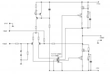
hehe-connection is just xformer,nothing more
it's just little cut'n'paste jobie,I didn't even delete incorrect feedback for that type of amp.......
regarding your question-everything is in DC symmetry.....additional resistors are handy -think of them as sort of source resistors for output fets.....
further tweaks can be with use of distortion meter,or (at least) with CRO and sig gene-looking for perfect AC symmetry in both halves
Paul Ebert:
T2 will be made up of 2 bifilar windings on a 250VA c-core, but at first i will use the secondaries of a Lundahl LL1623.
BR,
Anders
T2 will be made up of 2 bifilar windings on a 250VA c-core, but at first i will use the secondaries of a Lundahl LL1623.
BR,
Anders
Re: hi flg...
Hi John,
What happened to your project? Gone idle or worse?
Magura 🙂
carpenter said:I'm intrigued--but concerned... shouldn't your wire gauge be at least 18. Seems like 22 gauge will create a lot of resistance, thus heat. That is, unless your bias is much lower than 2x3 amps.
I'm very curious about the core. Where can I find more info regarding non-laminated cores?
Thanks,
John🙂
Hi John,
What happened to your project? Gone idle or worse?
Magura 🙂
Hi Magura,
My amp is a wonderful asset. This fact is certain. My guest listen to my two-way, mono set-up and offer comments of appreciation: "It sounds like your'e wearing headphones... It's so clear... smooth and silky"--and my all time favorite--"You made that??" etc.
Unfortunately, I injured my lower back and have been taking it easy for the last several weeks. The ZV7-T is too heavy to lift from the floor and work on🙂 For now, I listen to one channel, longing to construct the other. But, alas, that means I need to create another identical speaker to compliment the center channel I'm currently using. My bass cabinet weighs four times more than my amplifier! I remember having to roll the center channel bass cabinet up stairs several years ago. I'm just not healed up enough for a move like that. Ha. Probably will ask for help the next time.😀
I am grateful for the positive posts and exchange of information from you and the other members of this forum. This is what makes life on Earth wonderful: our friendships amid the chaos and political backdrop. When I'm reading what everyone here at DiyAudio is up to, I can forget for awhile the gathering storm...
Again, nice to hear from you. I can't wait to build some big air-core inductors. Several more months, perhaps.
John Inlow 🙂
Isn't it amazing how a couple of transistors can turn your world upside-down?😎
My amp is a wonderful asset.
This fact is certain. My guest listen to my two-way, mono set-up and offer comments of appreciation: "It sounds like your'e wearing headphones... It's so clear... smooth and silky"--and my all time favorite--"You made that??" etc.Unfortunately, I injured my lower back and have been taking it easy for the last several weeks. The ZV7-T is too heavy
to lift from the floor and work on🙂 For now, I listen to one channel, longing to construct the other. But, alas, that means I need to create another identical speaker to compliment the center channel I'm currently using. My bass cabinet weighs four times more than my amplifier! I remember having to roll the center channel bass cabinet up stairs several years ago. I'm just not healed up enough for a move like that. Ha. Probably will ask for help the next time.😀 I am grateful for the positive posts and exchange of information from you and the other members of this forum. This is what makes life on Earth wonderful: our friendships amid the chaos and political backdrop. When I'm reading what everyone here at DiyAudio is up to, I can forget for awhile the gathering storm...
Again, nice to hear from you. I can't wait to build some big air-core inductors. Several more months, perhaps.
John Inlow 🙂
Isn't it amazing how a couple of transistors can turn your world upside-down?😎
carpenter😱 How are you doing??? The Back and all...
I just recieved an 800VA Toriod... Just for the sake of knowing what I'm doing, I took it to work and measured it... approximately 275mH on each Pri. Cool, Over a Henry in series... Something a little ominuos about these numbers... Kinda like a Farad of C or something.
I actually want to build some kind of ZV8-ZV9 type thing first and use the toriod in the supply but, it would not take much to use one of my existing units and play inductor loading games...
What have you been up to? Any further inductor loading experimentation or comments???
I'm feeling much better, thank-you.
Hi flg,
I've started a small speaker business, and have been busy fabricating a mold for a 250hz tractrix horn. This, currently, consumes most of my free time.
The ZV7-T is awaiting its mate in order to operate in stereo mode.
I moved my stereo back into its original configuration and will eventually use the ZV7-T on the main L/R high frequency horns.
For now, InLow Sound is my primary concern.
Thanks for touching base with me.
John😀
BTW: I'm looking forward to further experimentation; air chokes, added resistors to ground on the outputs...
John, I finally jumped into my own adaption of T and J and SOZ 😀
Haven't attempted the susy part yet 😎 http://www.diyaudio.com/forums/showthread.php?s=&threadid=85246 I've reached a point were it is only sensible to follow your lead and build something
How are you doing Have you gone any further with you ZV7-T? Or have you tried the Air Core route ?
😀 😀 😀
Haven't attempted the susy part yet 😎 http://www.diyaudio.com/forums/showthread.php?s=&threadid=85246 I've reached a point were it is only sensible to follow your lead and build something
How are you doing
Have you gone any further with you ZV7-T? Or have you tried the Air Core route ?😀 😀 😀
Hi,
Flg, my sweetheart says she hears a hiss coming from the channel that my ZV7-T is connected to. Talk about embarrassing
I have a long interconnect (50 feet or so) and it may be contributing to the hiss. The amp is operating my center channel's high frequency horn and is located by the speaker, but the receiver is located behind me. I ran 50 feet of quality, 8 conductor phone wire to the amp -- one lead + one lead - the rest ground. Maybe it's a poor set-up. I can't hear a bit of hiss, but then again, I'm not the one with the "golden ears". I'll have to route a better wire -- Parts Express, here I come...
Sometime in the future (don't hold your breath) I will be experimenting with air-core chokes. I'm still amazed at this amp's ability to swing voltage. It doesn't get as hot as my other Pass/Grey experiments either. Like the Ax, it's far more direct than conventional amplifiers -- think of kissing a woman's hand with and without her wearing gloves. 😎 My 4 Hafler amps are so good, but don't compare to Nelson's stuff.
As for Inlow Sound, I have two home theater systems potentially sold. So far it's verbal, but looks positive. In my spare time, Inlow Sound's still my main squeeze -- right after Ellen, of course! 😉
BTW if anyone wants to watch an excellent video regarding the power of the mind and its ability to produce results, check out "The Secret" at www.thesecret.tv. I've watched this thing at least a dozen times! We all know this stuff, but somehow they make it larger than life.
Well, that's it for now, flg. Keep me up to date on your projects. I'll check out the hyperlink you just posted as well.
John😀
ordered new wire today
I'm going to run 22 gauge 2 conductor wire with foil shield. It may outperform my current configuration. What's odd is that the current configuration doesn't make my JBL amplifier hiss...
John
I'm going to run 22 gauge 2 conductor wire with foil shield. It may outperform my current configuration. What's odd is that the current configuration doesn't make my JBL amplifier hiss...
John
Well, all I can say other than, Phone Wire?, is, long runs are almost never good. You get inductance and capacitance you are not counting on or able to deal with easily. Depending on output and input Z's. You also get antena type action. The longer the wire the higher the induced unwanted voltage. I always used the shileded twisted pair Beldon stuff, but that's not always good for single ended connections. (ZV7-T is balanced, you run it that way don't you?) In the S.E. case a low loss coax type wire is good.
Got some bad news today. The inductor people who said "sure we can do that", got to calculating what I wanted and told me it would need 800cm^2 of core. 10"x10"!!! They asked what I was experimenting with and I told them an 800VA 120-240VAC Toroid Primary 😀 😀 😀 They only specialize in small stuff
So I'm learning about core material, tape cores etc.
I'm also trying to refine the design (including that 3 volt supply) and maybe a board layout or PtP configuration to get something going. Had to order some R's for the I source source. Got handfulls of small high power source R's but never have the value I need! I'll have some nice Heat Sinks in a week or so SK109s from Fischer Electronik. That should get me going. Can't do any wammy bammy chasis stuff, all my big tools are in storage  Actually, I have to figure out what box some of my transformers are in... I'm movin toward somethin 😀 😀 😀
Got some bad news today. The inductor people who said "sure we can do that", got to calculating what I wanted and told me it would need 800cm^2 of core. 10"x10"!!! They asked what I was experimenting with and I told them an 800VA 120-240VAC Toroid Primary 😀 😀 😀 They only specialize in small stuff
So I'm learning about core material, tape cores etc.
I'm also trying to refine the design (including that 3 volt supply) and maybe a board layout or PtP configuration to get something going. Had to order some R's for the I source source. Got handfulls of small high power source R's but never have the value I need!
I'll have some nice Heat Sinks in a week or so SK109s from Fischer Electronik. That should get me going. Can't do any wammy bammy chasis stuff, all my big tools are in storage Actually, I have to figure out what box some of my transformers are in... I'm movin toward somethin 😀 😀 😀- Status
- Not open for further replies.
- Home
- Amplifiers
- Pass Labs
- ZV7-T (transformer)