John,
Looking to the last schema I think we could find the bias in amps just seeing the voltage drop on R6.
Voltage drop/0.5 (R6) = Amps
Guess your circuit would need at least 2 Amps per device so a total of 4 amps or more. Shure enough R6 should be big😀
Looking to the last schema I think we could find the bias in amps just seeing the voltage drop on R6.
Voltage drop/0.5 (R6) = Amps
Guess your circuit would need at least 2 Amps per device so a total of 4 amps or more. Shure enough R6 should be big😀
One other thought, I guess R3 is used for biasing the output transistors and not necessary for feedback.
You also have a full loop Feedback to the gate of the input so a local FB to the output seems redundant.
If this is the case I would try biasing the output directly from the rail. Also R3 seems very low in value. Most of the feedback is going to the power FET and very little to the input.
You also have a full loop Feedback to the gate of the input so a local FB to the output seems redundant.
If this is the case I would try biasing the output directly from the rail. Also R3 seems very low in value. Most of the feedback is going to the power FET and very little to the input.
And yet another thought,
I see you are using quite a big C2, try using a very small one and very good quality, guess a 0.1 uf would be much better in sound specialy if you are using the amp over 400 hz.
I see you are using quite a big C2, try using a very small one and very good quality, guess a 0.1 uf would be much better in sound specialy if you are using the amp over 400 hz.
Wow, thanks for the input!
I hadn't thought of relocating R3 to the + rail. But you're right, feedback is already being applied to the input. I'll have to try this out. 10K is what Nelson used for R3, so I kept the value.
If you have other input, I'm all ears, errr, I guess I'm all eyes!
Thanks a million,
John😀
I hadn't thought of relocating R3 to the + rail. But you're right, feedback is already being applied to the input. I'll have to try this out. 10K is what Nelson used for R3, so I kept the value.
If you have other input, I'm all ears, errr, I guess I'm all eyes!
Thanks a million,
John😀
I was wondering about C2. I had thought of using 10 uF, but 0.1uF would probably offer cleaner highs? What's your favorite brand of cap in the 0.1uF range?
Again, thanks!
John🙂
Again, thanks!
John🙂
use the smallest one you can get away with for C2, of course this will affect the roll off of the amp (hi pass filter).
Size matters, but try different brands and sizes to see how this affects the sound, at least on other zen's this make a diference on sound and overall signature, generaly speaking a small coupling cap will show better highs.
Coming back to Nelson's comment I think he suggested a resistor at the output of the buffer, before C6, have you tested this?
On the R3 comment, I think if you are not looking for FB it should be in the order of 100 or 200K but you will also need to change the pot to a higher value to compensate and be able to set the bias you need. This change will also affect the gain of the amplifier.
May be, if you decide to test a higher value for R3 you would also like to lower the FB resistor to the input.
Regarding the R3 bias network, I got the impression that you get less distortion with lower resistance values. What's your take on this?
I can't recall off hand which Zen article I read this in, but I do remember reading it just the other day...
John🙂
btw, I'm still designing the buffer and have not yet given it a home. Soon...
I can't recall off hand which Zen article I read this in, but I do remember reading it just the other day...
John🙂
btw, I'm still designing the buffer and have not yet given it a home. Soon...
swapped IRFP240 for IRFP044N
Another good addition to this amplifier. I was able to lower the gain on my preamp by 35 percent or so. I can't tell a great deal of difference in the sound; the IRFP044 transistors are perhaps a bit creamer. But then again, we all know how our minds play tricks on us...
Almost all adjustments remained the same. I only had to lower P1 a fraction to get the DC offset down from 85mA to 14mA. I decided that was good enough for now. The slightest amount of torque on that shaft can send the offset sailing!
I'll let those in my home with the "golden ears" offer the final analysis.
John🙂
So, John, are these the IRFP044N transistors your talking about??? I asked some time ago, and I order a handfull, But, I've been busy... They have similar gain and lower C😀 I'll be trying them too... Sounded good to me...
Hi flg,
I'm not so certain about the lower capacitance, I thought the 044N were similar to the 244 series. The 044N series does have greater transconductance which shows up as increased gain, thus allowing me to reduce the output setting on my electronic x-over.
Besides the greater transconductance, I feel compelled by the notion that if I'm running the transistor closer to its voltage limits it'll sound better. I remember N.P. suggesting that the 244 transistors sound better with greater voltages. Perhaps, I thought, the same would hold true to the 044N transistors. Since the ZV7-T swings 47 volts (my version anyway) the 044N should be reaching well into it voltage capabilities.
I listened to my system in home theater mode playing Star-Wars 3 last night. The center channel offered an extremely pleasant listening experience. I'm so impressed.
A fellow (my cousin's boyfriend) who I've only recently become acquainted with is very interested in what I've managed to accomplish. He likes the sound so much that I think we have another N.P. convert!
Good luck with your project. Keep me posted on the results.
John🙂
John,
Coming back to thoughts on R3, the idea of using a higher value for this resistor was to lower the FB to the output FET and replacing it with more FB to the buffer meaning using a lower FB resistor to the input to compensate to your taste.
To my understanding this is a more generalized application practice, I guess due to better results soundwise, you could go as far as eliminating FB altogether to the output by means of a high value resistor or connecting R3 to the rail, just an idea.
Hi apassgear,
I like your idea of routing R3 to the + rail.
I just love the sound of my amp since I switched transistors. The IRFP044N transistors are much smoother sounding than the 244 series.
The "golden ears" in my family finally have given this amp the "nod".
John
I like your idea of routing R3 to the + rail.
I just love the sound of my amp since I switched transistors. The IRFP044N transistors are much smoother sounding than the 244 series.
The "golden ears" in my family finally have given this amp the "nod".

John
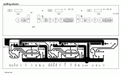
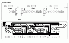
In the drawing, previous post, the symbol for the buffer transistor is backwards on the stuffing artwork. Sorry. The labeling for the gds is correct. Just flip the transistor symbol around if you decide to put it to use.
John🙂
John🙂
Hi all,
Looks like a one-man rant here. Ha.
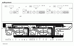
I reconfigured the pcb artwork through Express PCBs software and now I'm in the process of ordering pcbs.
A pair of double-sided, plated through holes, but NO solder-mask or silk-screen will cost me $107.00 for the first pair. I figure that diy-ing a pair will cost at least that much in time and materials -- not to mention that I'm anxious to see if this works. Turn around time is short; I believe it's three or four days, and that including the shipping.
If anyone feels inclined to bite-the-bullet with me, they can save me some cash -- at least I'm being honest, huh...
The break-down:
2 boards @ 107.00
4 boards @ 138.00
6 boards @ 169.25
8 boards @ 202.70
10 boards @ 233.00
... and it just gets better and better.
Anyway, just thought I'd offer. You should check my work first -- wouldn't want anyone sending me hate mail, taking a leak on my poor ol' dad's grave, etc...
John🙂
Looks like a one-man rant here. Ha.
I reconfigured the pcb artwork through Express PCBs software and now I'm in the process of ordering pcbs.
A pair of double-sided, plated through holes, but NO solder-mask or silk-screen will cost me $107.00 for the first pair. I figure that diy-ing a pair will cost at least that much in time and materials -- not to mention that I'm anxious to see if this works. Turn around time is short; I believe it's three or four days, and that including the shipping.
If anyone feels inclined to bite-the-bullet with me, they can save me some cash -- at least I'm being honest, huh...
The break-down:
2 boards @ 107.00
4 boards @ 138.00
6 boards @ 169.25
8 boards @ 202.70
10 boards @ 233.00
... and it just gets better and better.
Anyway, just thought I'd offer. You should check my work first -- wouldn't want anyone sending me hate mail, taking a leak on my poor ol' dad's grave, etc...

John🙂
- Status
- Not open for further replies.
- Home
- Amplifiers
- Pass Labs
- ZV7-T (transformer)


 I just discovered that I got the drain and the gate switched on the little buffer transistor. Here's another correction. I promise never to post again...