It's just so cool...
Nelson's ideas and articles just flame my brain. I just can't get enough. Talk about addiction! It's better than women, whiskey, and song, unless that song is playing through my amplifier. Gosh, I can't see how this baby is going to get any better, jfet of not. I can place my ear against my 110 db 1w1m horn and hear nothing but air. Nice, quite air. That's no joke! I think this inductor loading must also be doing double duty as a filter. I'm running an LCLC filter, but to be this quiet, there's got to be more to it than my simple filter. Oh yes, the amp design. It all works. I could never get my AX this quiet, sweet baby that it is.
flg, somewhere around here I posted a drawing of an inductor loaded version of Nelson's jfet amp in simple balanced mode. It's been given an ok from several members and Nelson has suggested it looks possible. I'm learning how to build the ZV7-T as a prelude to the jfet project. It'd be nice to have others on board to brainstorm with. Glad you're here, along with Choky, Maqura, apassgear, nobody special, Nelson and the rest of the viewing gang. I'm sorry if I missed anyone else.
John🙂
Re: inductance
John,
I'm not quite sure but it seems to me that whatever coils you use should share the same magnetic path, this would mean that you will not be able to use two separate coils. Maybe a bifilar winding with center tap could be used and both sides should measure similar inductance as does your Piltron.
The way you mount the coil also has influence on the inductace. As an example if one side is near a ferromagnetic material it will show a higher inductance than the other side that could not be near a similar field.
Me thinks, for what you say, that you have gone far enough with your project and any improvement will have diminishing returns and maybe you will only hear some differences with no clear winner, or to be honest you will return to the Piltron. Time to move on to a new project?
A Pi filter as you describe on the PSU its realy good so is no surprise to hear your comments.
Excellent work John, congratulations!!!😎 😎 😎
carpenter said:That's really not so tough to transfer into air chokes. Is 4.66 ohms resistance per choke too much. I'm looking at 16 gauge wire. This yields a choke with the dimensions of 1" dia. core, 1" width, 6.89" outer dia. It will take two of these babies per mono-block. They could be placed side by side and connected like a center tapped plitron to cancel magnetics. Or is this totally unnecessary.
😀
John,
I'm not quite sure but it seems to me that whatever coils you use should share the same magnetic path, this would mean that you will not be able to use two separate coils. Maybe a bifilar winding with center tap could be used and both sides should measure similar inductance as does your Piltron.
The way you mount the coil also has influence on the inductace. As an example if one side is near a ferromagnetic material it will show a higher inductance than the other side that could not be near a similar field.
Me thinks, for what you say, that you have gone far enough with your project and any improvement will have diminishing returns and maybe you will only hear some differences with no clear winner, or to be honest you will return to the Piltron. Time to move on to a new project?
A Pi filter as you describe on the PSU its realy good so is no surprise to hear your comments.
Excellent work John, congratulations!!!😎 😎 😎
For 20Hz you need 80mH, to keep things reasonably efficient you need less than 3ohm for the inductor. my air core 80mH inductors are around 2.4ohm as I recall it.
Magura 🙂
Magura 🙂
hi!
I have used the secondary of a good tube output transformer (LL1627 PP) for a similar task with very good results. It has a c-core with a small air gap to give some dc current imbalance immunity. The dc resistance is in the range of 0.5 ohms.
BR,
Anders
I have used the secondary of a good tube output transformer (LL1627 PP) for a similar task with very good results. It has a c-core with a small air gap to give some dc current imbalance immunity. The dc resistance is in the range of 0.5 ohms.
BR,
Anders
80mh?
Maguara, 80mH is so much easier. But, I thought your 2x80 weighed 20kg. Here's what I got off the net:
Inductance 160.36 mH
DC Resistance 2.16 Ohms
Wire Gauge 12 AWG
Wire Diameter 80.8 mils (1 mil = .001 in)
Coil Length 2 in
Coil Inner Diameter 1 in
Coil Outer Diameter 8.43 in
Average Turn Diameter 4.57 in
Wire Length 1336.32 feet
Copper Weight 26.41 pounds
Turns 1118
Levels 45.17
Turns/Level 24.75
At 26.41 pounds, I can do this. Isn't this about half the weight you mentioned?
Thanks for posting,
John🙂
bappe,
That's just the kind of info I love to read. I'll check into that serial number you posted.
John🙂
apassgear, thanks for the positive strokes. With regards to transformer strategy, I'm giving this experiment my all in order to prepare myself for the ZV9-T. If I'm going to make mistakes, it's probably easier to understand them with this simple little layout. The ZV9-T will be more confusing for me. That is, unless one of you fine gents build and debug it first. Ha ha ha, there's a muhaahaa in there somewhere...
love you guys, what an amazing group of explorers.
John😀
Your calculations are most likely right, but you will find that inner diameter of 25mm and 1.9mm wire does not add up. Besides that you don't need 160mH but 2*80mH. To actually wind a bifilar coil is pretty hard in the first place, you need a reasonable inner diameter to end up with something useful.
I am at my GF's place 400km from home at this moment, but when I get home Monday or Tuesday I will try if I can post a pic of my inductors, then you will see what I'm trying to explain.
Magura 🙂
I am at my GF's place 400km from home at this moment, but when I get home Monday or Tuesday I will try if I can post a pic of my inductors, then you will see what I'm trying to explain.
Magura 🙂
Zv7-taxj?
Oh, please do elaborate.
The 160 mH is a center tapped 2x80 choke.
John🙂
For center tap, I'll be hand winding two strands onto one bobbin. Twelve gauge will just take a bit longer. I'll wear gloves!
Oh, please do elaborate.
The 160 mH is a center tapped 2x80 choke.
John🙂
For center tap, I'll be hand winding two strands onto one bobbin. Twelve gauge will just take a bit longer. I'll wear gloves!
Re: Zv7-taxj?
You will find gloves to be a disadvantage, as they will cause you more trouble than you could possibly imagine when it comes to controlling the wires and pulling them hard enough to make a good quality inductor 🙁
T(inductor load) A(aleph current source) J(J-fet cascoded) X(super symmetry)
Magura 🙂
carpenter said:Oh, please do elaborate.
I'll wear gloves!
You will find gloves to be a disadvantage, as they will cause you more trouble than you could possibly imagine when it comes to controlling the wires and pulling them hard enough to make a good quality inductor 🙁
T(inductor load) A(aleph current source) J(J-fet cascoded) X(super symmetry)
Magura 🙂
I agree with Magura, 1 inch internal dia is not a good combination, the aspect ratio of a coil has a lot to do with induction. If you start from a bigger core you will find that you can get to the induction you want with fewer turns.
If I were you I would trade some of the Rdc of the coil by a more compact aspect ratio and use say 14 ga wire. The overall eficiency of the coil will be better meaning less turns for the given intuctance you want, so the trade off on Rdc will be less than what you think.
Do you have an inductance bridge John?
When coiling heavy wire I use Masking tape over the fingers I use 😀
inductor calculator
This is the web page I use to calculate my inductor size. It suggests that a small core uses less copper than a large core. Try out several core sizes for the same mH and tell me what you think. Maybe the software is wrong. I'm a carpenter with a great bunch of audio friends. I trust your judgement.
apassgear, what is an inductor bridge? I appologize for my ignorance. Masking tape, cool idea.
John Inlow🙂
It says "this page cannot be found", which is wrong as the page is right there in front of you. Also, hit the arrow in the upper right hand corner; it takes you to a page loaded with goodies.
www.lalena.com/audio/calculator/inductor/
The Lalena calculator have caused me a great deal of trouble. Something doesn't add up, or I'm crap at winding 😉
I use a small DOS based calculator, works real good. I will give you the name of it when I get back home.
I can also give you the dimensions of the coils I made for the purpose, I played a lot with the figures before I chose the final solution. As I told earlier I chose 1.9mm wire, in order to keep the DCR down, I never paid much attention to anything but the electrical properties and the practical issues according to actually winding the coil.
Magura 🙂
Thanks, Magura
I've located another calculator on line and it is more in agreement with you. For 80 mH, it suggests 2.45" height with 4.9" radius and 472 turns.
Thanks for offering to share your findings with me.
John😀
I've located another calculator on line and it is more in agreement with you. For 80 mH, it suggests 2.45" height with 4.9" radius and 472 turns.
Thanks for offering to share your findings with me.
John😀
Off the top of my head I made my 80mH inductors with 550 turns.
Are you going to wind you own?
Magura 🙂
Are you going to wind you own?
Magura 🙂
John and Magura,
As you, I have also made many coils, air core and cored, I do have an inductance bridge (that serves to measure inductance of course). One can make different aspect ratio coils with the same inductance and they will have different amount of turns using the same Gage wire. Depends also on how tight you pack the wire on the coil. So you can have the 80 mH with 1000 or 478 or whatever turns.
As to my previous point, from John’s link, look at the following results using only 16 gage you get at 80 mH with 3.58 Rdc with only 6.83 pounds of copper, assuming the calculator works well.
Inductance 80.15 mH
DC Resistance 3.58 Ohms
Wire Gauge 16 AWG
Wire Diameter 50.8 mils (1 mil = .001 in)
Coil Length 2 in
Coil Inner Diameter 2 in
Coil Outer Diameter 4.64 in
Average Turn Diameter 3.27 in
Wire Length 874.04 feet
Copper Weight 6.83 pounds
Turns 1022
Levels 25.96
Turns/Level 39.37
16 AWG has 2,583 circular mils, so this coil could work well up to some 2 or even 2.5 Amps on a ventilated surrounding.
Hi guys,
Magura and appassgear, good to hear from you. Just got home from some volunteer work. Tired, but ever so happy to read your posts.
I will wind my own coils. I'm either going to fabricate a winder, or purchase a small motorized unit. I'm trying to get into the speaker business (I have a design that flat out knocks my socks off) and I'm going to require a winder to wind the chokes in my x-overs.
I have just recently purchased an inductance/capacitance meter to measure inductance.
I'm anxious to wind two large center tapped chokes for my upcoming ZV9-T project. Won't that be a blast. Naturally, I'm anxious to learn as much as possible from you guys.
Many thanks for your time,
John🙂
coil winder
You won't get far wit a small motorised unit, as you will need a quite powerfull unit to wind 2*1.9mm wire. The best way to do it "low budget" is to use a lathe. I have a winding machine for smaller coils, but I use a lathe for anything over 1mm wire.
All you have to do is to make a rev. counter, such can be purchased as a complete unit, or made of a calculator and a switch. I have chosen the calculator solution, as it can count parts of a rev.
Magura 🙂
a lathe...
Now, that's a really good idea! I see that Harbor Freight has them on sale from time to time. I knew I should have purchased one last year.
The revolutions counter sounds terrific. Care to share your design?
Thanks,
John Inlow🙂
Now, that's a really good idea! I see that Harbor Freight has them on sale from time to time. I knew I should have purchased one last year.
The revolutions counter sounds terrific. Care to share your design?
Thanks,
John Inlow🙂
John,
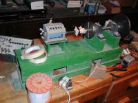
This is what I use for my DIY work. It has a core shaft where I mount different forms made of wood or solid steel. It has a rev counter attached to the shaft with ¼” rubber hose. Initially it was design with the idea to motorize it but never came to do that. I have work 12 gage wire over rectangular forms, which is more demanding that round forms, not easy though with that heavy wire.
This is what I use for my DIY work. It has a core shaft where I mount different forms made of wood or solid steel. It has a rev counter attached to the shaft with ¼” rubber hose. Initially it was design with the idea to motorize it but never came to do that. I have work 12 gage wire over rectangular forms, which is more demanding that round forms, not easy though with that heavy wire.
Attachments
- Status
- Not open for further replies.
- Home
- Amplifiers
- Pass Labs
- ZV7-T (transformer)