Hello lutkeveld
I am using a Li-Ion battery pack 18650 6s3p with onboard BMS. It outputs less than 25v. It is similar to this one:
2021 new 6s3p 24 V 18650 Li ion battery 25.2 V 19800 MAH E bike, moped / electric / Li ion battery pack with charger for sale|Battery Packs| - AliExpress
I have just tried the amplifier with a 19v laptop brick (smps I presume). The standby noise is the same.
The hissing/whine increases when the volume knob is turned up.
My speakers are 4x FaitalPRO 4FE32 4ohm 91dB in stereo dipole configuration.
A fix is needed. It is not really liveable with as it is. Any ideas would be appreciated.
Hello Lutkeveld
That is great news. We will place an order from your homepage.
Kind regards
Jimmy, ACE monitors
That is great news. We will place an order from your homepage.
Kind regards
Jimmy, ACE monitors
The pre-order page of the AIO438 just went live!
ZOUDIO AIO438 - Z O U D I O
https://ibb.co/GvzhXz5
A small recap of the improvements over the AIO4CH:
The AIO438 is based around the same amplifier chip as the AIO4CH but adds a list of improvements:
1) Upgrade to BT5.0
Improves the sound quality, range and power consumption.
2) Onboard antenna
Ideal for compact installations. Connecting an external antenna is still possible.
3) Onboard USB-C port
So the board can be reprogrammed without the need for external programmers.
4) Improved configuration tool
Easier to use with faster upload speed and a more robust data transfer protocol. The beta version has been send out quite some time ago, and the feedback is good. Currently it is released with a limited feature set. The version with a full feature set will be released together with the AIO438.
The amplifier will be released with the same functionality as the AIO4CH minus the TrueWirelessStereo function.
For those interested, there will be a developer software package available, which allows developers to access the firmware of the bluetooth module. There are multiple features that are nice to have (USB soundcard, SPDIF, TWS), but too time intensive to include at the release date. Hopefully with the help of other community members we can expand the functionality over time and release the updates to other users. If you want access to this package, leave a note in your order at checkout.
The amplifier will start to ship on the 14th of januari in order of payment.
Again, have a look for yourself on the productpage:
ZOUDIO AIO438 - Z O U D I O
Looks interesting! When will the 2.0 version of the software be available for download? I would like to try it out first. I am also considering a JAB5 Sure board with Sigma studio software and at first glance your design looks nicer
I added a JLSounds USB to I2S board, to my 1st Zoudio amp. It's a reasonably high end converter board, which I paid as much for as the Zoudio amp to get.
The 3 terminal regulator is to take advantage of it providing galvanic isolation from the USB side - preventing all those switching brick powered PC generated superfluous nastiness from getting into the I2S side. Which, along with the amp, is powered by all linear.
I just got it hooked up; havent even mounted the boards yet...Sounds absolutely marvelous! Xmas present to myself, as who in my world would even know I'd like to have a JLS USB to I2S board of all things?
This is just to document another USB to I2S board working with the V1 version. Here's to the probability of the V2 sounding just as good over BT 5.0 - with the galvanic isolation from the music source that connection provides ;')
Attachments
I used ZOUDIO aio4ch to power two satellites and a subwoofer. The subwoofer uses Channel 3 and 4 in combination. I was able to configure the system with mono input (the stereo firmware update was not available yet) and it worked like a charm! The bluetooth module was a convenient source for the signal and with some measurements and a couple of filters the whole setup sounded very nice.
The idea was to install the amplifier board with its 24V power supply in the back of the subwoofer. The volume should always stay at maximum because I wanted to control the volume from the source (smartphone or PC). I was not concerned about overheating because the specs of the board say it has a thermal protection.
The setup worked quite good for about two hours (enough time for several measurements and adjustments). After that it suddenly stopped to make any sound. The amplifier chip seemed to have burned through.
I returned the board and I got a replacement without trouble (thanks for that!). I thought the board must have hat a manufacturing error which ouccurs randomly. This is no big deal if it is replaced swiftly and without problems.
So after I got the replacement board I reinstalled the whole setup and again it worked flawlessly and sounded quite good. I measured and adjusted again for about 1:30h. After that the speakers suddenly failed. The error was not exactly the same as with the first board because the subwoofer was still working. But the second board seemed to have failed in a very similar way.
Again I got a replacement. I appreciate this very much! However after loosing two boards I wonder if the problem really was a random manufacturing error. What if the thermal protection is not working? Should I add some heatsinks to the amplifier chips? Could there be a wiring issue that destroys the board after running perfectly for more than an hour?
Before I wire up the new board I wanted to ask for your opinions on this topic. I think I made no mistake with the wiring (it worked after all) but maybe I'm missing something. I do not want to loose another amplifier...
connecting two channels in parallel is highly discouraged. i don't think they sent you two bad boards .. with good reason i think the problem is combining multiple channelsI used ZOUDIO aio4ch to power two satellites and a subwoofer. The subwoofer uses Channel 3 and 4 in combination. I was able to configure the system with mono input (the stereo firmware update was not available yet) and it worked like a charm! The bluetooth module was a convenient source for the signal and with some measurements and a couple of filters the whole setup sounded very nice.
The idea was to install the amplifier board with its 24V power supply in the back of the subwoofer. The volume should always stay at maximum because I wanted to control the volume from the source (smartphone or PC). I was not concerned about overheating because the specs of the board say it has a thermal protection.
The setup worked quite good for about two hours (enough time for several measurements and adjustments). After that it suddenly stopped to make any sound. The amplifier chip seemed to have burned through.
I returned the board and I got a replacement without trouble (thanks for that!). I thought the board must have hat a manufacturing error which ouccurs randomly. This is no big deal if it is replaced swiftly and without problems.
So after I got the replacement board I reinstalled the whole setup and again it worked flawlessly and sounded quite good. I measured and adjusted again for about 1:30h. After that the speakers suddenly failed. The error was not exactly the same as with the first board because the subwoofer was still working. But the second board seemed to have failed in a very similar way.
Again I got a replacement. I appreciate this very much! However after loosing two boards I wonder if the problem really was a random manufacturing error. What if the thermal protection is not working? Should I add some heatsinks to the amplifier chips? Could there be a wiring issue that destroys the board after running perfectly for more than an hour?
Before I wire up the new board I wanted to ask for your opinions on this topic. I think I made no mistake with the wiring (it worked after all) but maybe I'm missing something. I do not want to loose another amplifier...
Combining two channels is explicitly listed in the specification. The board is made for that. Also keep in mind that the point of failure was in both cases the chip with the separate channels.connecting two channels in parallel is highly discouraged. i don't think they sent you two bad boards .. with good reason i think the problem is combining multiple channels
The two channels weren't simply connected in parallel, but combined in "DUAL Mode"... which is explicitly setup and wired like the manual described.
I an trying to install the firmware with auto startup. I want a plain version with only analogue aux in. Therefore i have a ordinary potmeter.
It will not accept the firmware?
Does anyone have a clue?
CONNECT THE PROGRAMMER TO THE BOTTOM ROW OF THE PROGRAMMING HEADER
BOARD CAN BE PROGRAMMED WITHOUT PSU/BATTERY CONNECTED
CONNECTED
UPDATING FIRMWARE TO: ATMEGA328PB_1.1.6_DEFAULT_ON.HEX
PLEASE WAIT 30 SECONDS. LEDS ON PROGRAMMER SHOULD BE FLASHING
DISCONNECTED
avrdude: Version 6.3-20171130
Copyright (c) 2000-2005 Brian Dean, http://www.bdmicro.com/
Copyright (c) 2007-2014 Joerg Wunsch
System wide configuration file is ".\avrdude\avrdude.conf"
Using Port : COM3
Using Programmer : arduino
Overriding Baud Rate : 38400
avrdude: stk500_recv(): programmer is not responding
avrdude: stk500_getsync() attempt 1 of 10: not in sync: resp=0xd3
avrdude: stk500_recv(): programmer is not responding
avrdude: stk500_getsync() attempt 2 of 10: not in sync: resp=0xd3
avrdude: stk500_recv(): programmer is not responding
avrdude: stk500_getsync() attempt 3 of 10: not in sync: resp=0xd3
avrdude: stk500_recv(): programmer is not responding
avrdude: stk500_getsync() attempt 4 of 10: not in sync: resp=0xd3
avrdude: stk500_recv(): programmer is not responding
avrdude: stk500_getsync() attempt 5 of 10: not in sync: resp=0xd3
avrdude: stk500_recv(): programmer is not responding
avrdude: stk500_getsync() attempt 6 of 10: not in sync: resp=0xd3
avrdude: stk500_recv(): programmer is not responding
avrdude: stk500_getsync() attempt 7 of 10: not in sync: resp=0xd3
avrdude: stk500_recv(): programmer is not responding
avrdude: stk500_getsync() attempt 8 of 10: not in sync: resp=0xd3
avrdude: stk500_recv(): programmer is not responding
avrdude: stk500_getsync() attempt 9 of 10: not in sync: resp=0xd3
avrdude: stk500_recv(): programmer is not responding
avrdude: stk500_getsync() attempt 10 of 10: not in sync: resp=0xd3
avrdude done. Thank you.
UPDATE FAILED
CONNECTED
i did several tests and plugged out and in the small usb interface on the board
this is the result so far:
CONNECT THE PROGRAMMER TO THE BOTTOM ROW OF THE PROGRAMMING HEADER
BOARD CAN BE PROGRAMMED WITHOUT PSU/BATTERY CONNECTED
CONNECTED
INPUT: OFF
UPLOAD STARTED
OUTPUT: ECHO
OUTPUT: ECHO
OUTPUT: ECHO
INPUT: ON
OUTPUT: ECHO
INPUT: ECHO
OUTPUT: MODEL
INPUT: AIO4CH
OUTPUT: FIRMWARE
INPUT: 1.1.6
OUTPUT: EEPROM BEGIN
OUTPUT: VOLSTART -30
OUTPUT: VOLMAX 0
OUTPUT: POWERLOW 0
OUTPUT: POWERSHUTDOWN 0
OUTPUT: I2C AMP1 0X8C 0X0B 0X14 0X0 0X40 0X26 0XE7 0X0 0X40 0X26 0XE7
OUTPUT: I2C AMP2 0X8C 0X0B 0X14 0X0 0X40 0X26 0XE7 0X0 0X40 0X26 0XE7
OUTPUT: I2C DUAL 0XAA 0X01 0X30 0X8 0X0 0X0 0X0 0X0 0X0 0X0 0X0 0X0 0X0 0X0 0X0 0X0 0X0 0X0 0X0 0X0 0X0 0X0 0X0
OUTPUT: I2C DUAL 0XAA 0X01 0X44 0X8 0X0 0X0 0X0 0X0 0X0 0X0 0X0 0X0 0X0 0X0 0X0 0X0 0X0 0X0 0X0 0X0 0X0 0X0 0X0
OUTPUT: I2C DUAL 0XAA 0X01 0X58 0X8 0X0 0X0 0X0 0X0 0X0 0X0 0X0 0X0 0X0 0X0 0X0 0X0 0X0 0X0 0X0 0X0 0X0 0X0 0X0
OUTPUT: I2C DUAL 0XAA 0X01 0X6C 0X8 0X0 0X0 0X0 0X0 0X0 0X0 0X0 0X0 0X0 0X0 0X0 0X0 0X0 0X0 0X0 0X0 0X0 0X0 0X0
OUTPUT: I2C DUAL 0XAA 0X02 0X08 0X8 0X0 0X0 0X0 0X0 0X0 0X0 0X0 0X0 0X0 0X0 0X0 0X0 0X0 0X0 0X0 0X0 0X0 0X0 0X0
OUTPUT: I2C DUAL 0XAA 0X02 0X1C 0X8 0X0 0X0 0X0 0X0 0X0 0X0 0X0 0X0 0X0 0X0 0X0 0X0 0X0 0X0 0X0 0X0 0X0 0X0 0X0
OUTPUT: I2C DUAL 0XAA 0X02 0X30 0X8 0X0 0X0 0X0 0X0 0X0 0X0 0X0 0X0 0X0 0X0 0X0 0X0 0X0 0X0 0X0 0X0 0X0 0X0 0X0
OUTPUT: I2C DUAL 0XAA 0X02 0X44 0X8 0X0 0X0 0X0 0X0 0X0 0X0 0X0 0X0 0X0 0X0 0X0 0X0 0X0 0X0 0X0 0X0 0X0 0X0 0X0
OUTPUT: I2C DUAL 0XAA 0X02 0X58 0X8 0X0 0X0 0X0 0X0 0X0 0X0 0X0 0X0 0X0 0X0 0X0 0X0 0X0 0X0 0X0 0X0 0X0 0X0 0X0
OUTPUT: I2C DUAL 0XAA 0X02 0X6C 0X8 0X0 0X0 0X0 0X0 0X0 0X0 0X0 0X0 0X0 0X0 0X0 0X0 0X0 0X0 0X0 0X0 0X0 0X0 0X0
OUTPUT: I2C DUAL 0XAA 0X03 0X08 0X8 0X0 0X0 0X0 0X0 0X0 0X0 0X0 0X0 0X0 0X0 0X0 0X0 0X0 0X0 0X0 0X0 0X0 0X0 0X0
OUTPUT: I2C DUAL 0XAA 0X03 0X1C 0X8 0X0 0X0 0X0 0X0 0X0 0X0 0X0 0X0 0X0 0X0 0X0 0X0 0X0 0X0 0X0 0X0 0X0 0X0 0X0
OUTPUT: I2C DUAL 0XAA 0X03 0X30 0X8 0X0 0X0 0X0 0X0 0X0 0X0 0X0 0X0 0X0 0X0 0X0 0X0 0X0 0X0 0X0 0X0 0X0 0X0 0X0
OUTPUT: I2C_EQ DUAL 0XAA 0X03 0X44 0X8 0X0 0X0 0X0 0X0 0X0 0X0 0X0 0X0 0X0 0X0 0X0 0X0 0X0 0X0 0X0 0X0 0X0 0X0 0X0
OUTPUT: I2C_EQ DUAL 0XAA 0X03 0X58 0X8 0X0 0X0 0X0 0X0 0X0 0X0 0X0 0X0 0X0 0X0 0X0 0X0 0X0 0X0 0X0 0X0 0X0 0X0 0X0
OUTPUT: I2C DUAL 0XAA 0X15 0X34 0X8 0X0 0X0 0X0 0X0 0X0 0X0 0X0 0X0 0X0 0X0 0X0 0X0 0X0 0X0 0X0 0X0 0X0 0X0 0X0
OUTPUT: I2C DUAL 0XAA 0X15 0X48 0X8 0X0 0X0 0X0 0X0 0X0 0X0 0X0 0X0 0X0 0X0 0X0 0X0 0X0 0X0 0X0 0X0 0X0 0X0 0X0
OUTPUT: I2C DUAL 0XAA 0X15 0X5C 0X8 0X0 0X0 0X0 0X0 0X0 0X0 0X0 0X0 0X0 0X0 0X0 0X0 0X0 0X0 0X0 0X0 0X0 0X0 0X0
OUTPUT: I2C DUAL 0XAA 0X15 0X70 0X8 0X0 0X0 0X0 0X0 0X0 0X0 0X0 0X0 0X0 0X0 0X0 0X0 0X0 0X0 0X0
OUTPUT: I2C DUAL 0XAA 0X16 0X08 0X0 0X0 0X0 0X0
OUTPUT: I2C AMP1 0XAA 0X0F 0X10 0X8 0X0 0X0 0X0 0X0 0X0 0X0 0X0 0X0 0X0 0X0 0X0 0X0 0X0 0X0 0X0 0X0 0X0 0X0 0X0
OUTPUT: I2C AMP1 0XAA 0X0F 0X24 0X8 0X0 0X0 0X0 0X0 0X0 0X0 0X0 0X0 0X0 0X0 0X0 0X0 0X0 0X0 0X0 0X0 0X0 0X0 0X0
OUTPUT: I2C AMP1 0XAA 0X0F 0X38 0X8 0X0 0X0 0X0 0X0 0X0 0X0 0X0 0X0 0X0 0X0 0X0 0X0 0X0 0X0 0X0 0X0 0X0 0X0 0X0
OUTPUT: I2C AMP1 0XAA 0X0F 0X4C 0X8 0X0 0X0 0X0 0X0 0X0 0X0 0X0 0X0 0X0 0X0 0X0 0X0 0X0 0X0 0X0 0X0 0X0 0X0 0X0
OUTPUT: I2C AMP1 0XAA 0X0F 0X60 0X8 0X0 0X0 0X0 0X0 0X0 0X0 0X0 0X0 0X0 0X0 0X0 0X0 0X0 0X0 0X0 0X0 0X0 0X0 0X0
OUTPUT: I2C AMP1 0XAA 0X0F 0X74 0X8 0X0 0X0 0X0 0X0 0X0 0X0 0X0 0X0 0X0 0X0 0X0
OUTPUT: I2C AMP1 0XAA 0X10 0X08 0X0 0X0 0X0 0X0 0X0 0X0 0X0 0X0
OUTPUT: I2C AMP1 0XAA 0X10 0X10 0X8 0X0 0X0 0X0 0X0 0X0 0X0 0X0 0X0 0X0 0X0 0X0 0X0 0X0 0X0 0X0 0X0 0X0 0X0 0X0
OUTPUT: I2C AMP1 0XAA 0X10 0X24 0X8 0X0 0X0 0X0 0X0 0X0 0X0 0X0 0X0 0X0 0X0 0X0 0X0 0X0 0X0 0X0 0X0 0X0 0X0 0X0
OUTPUT: I2C AMP1 0XAA 0X10 0X38 0X8 0X0 0X0 0X0 0X0 0X0 0X0 0X0 0X0 0X0 0X0 0X0 0X0 0X0 0X0 0X0 0X0 0X0 0X0 0X0
OUTPUT: I2C AMP1 0XAA 0X10 0X4C 0X8 0X0 0X0 0X0 0X0 0X0 0X0 0X0 0X0 0X0 0X0 0X0 0X0 0X0 0X0 0X0 0X0 0X0 0X0 0X0
OUTPUT: I2C AMP2 0XAA 0X0F 0X10 0X8 0X0 0X0 0X0 0X0 0X0 0X0 0X0 0X0 0X0 0X0 0X0 0X0 0X0 0X0 0X0 0X0 0X0 0X0 0X0
OUTPUT: I2C AMP2 0XAA 0X0F 0X24 0X8 0X0 0X0 0X0 0X0 0X0 0X0 0X0 0X0 0X0 0X0 0X0 0X0 0X0 0X0 0X0 0X0 0X0 0X0 0X0
OUTPUT: I2C AMP2 0XAA 0X0F 0X38 0X8 0X0 0X0 0X0 0X0 0X0 0X0 0X0 0X0 0X0 0X0 0X0 0X0 0X0 0X0 0X0 0X0 0X0 0X0 0X0
OUTPUT: I2C AMP2 0XAA 0X0F 0X4C 0X8 0X0 0X0 0X0 0X0 0X0 0X0 0X0 0X0 0X0 0X0 0X0 0X0 0X0 0X0 0X0 0X0 0X0 0X0 0X0
OUTPUT: I2C AMP2 0XAA 0X0F 0X60 0X8 0X0 0X0 0X0 0X0 0X0 0X0 0X0 0X0 0X0 0X0 0X0 0X0 0X0 0X0 0X0 0X0 0X0 0X0 0X0
OUTPUT: I2C AMP2 0XAA 0X0F 0X74 0X8 0X0 0X0 0X0 0X0 0X0 0X0 0X0 0X0 0X0 0X0 0X0
OUTPUT: I2C AMP2 0XAA 0X10 0X08 0X0 0X0 0X0 0X0 0X0 0X0 0X0 0X0
OUTPUT: I2C AMP2 0XAA 0X10 0X10 0X8 0X0 0X0 0X0 0X0 0X0 0X0 0X0 0X0 0X0 0X0 0X0 0X0 0X0 0X0 0X0 0X0 0X0 0X0 0X0
OUTPUT: I2C AMP2 0XAA 0X10 0X24 0X8 0X0 0X0 0X0 0X0 0X0 0X0 0X0 0X0 0X0 0X0 0X0 0X0 0X0 0X0 0X0 0X0 0X0 0X0 0X0
OUTPUT: I2C AMP2 0XAA 0X10 0X38 0X8 0X0 0X0 0X0 0X0 0X0 0X0 0X0 0X0 0X0 0X0 0X0 0X0 0X0 0X0 0X0 0X0 0X0 0X0 0X0
OUTPUT: I2C AMP2 0XAA 0X10 0X4C 0X8 0X0 0X0 0X0 0X0 0X0 0X0 0X0 0X0 0X0 0X0 0X0 0X0 0X0 0X0 0X0 0X0 0X0 0X0 0X0
OUTPUT: I2C AMP1 0X8C 0X0E 0X7C 0X0 0X0 0X0 0X0
OUTPUT: I2C AMP1 0X8C 0X0F 0X0C 0X0 0X0 0X0 0X0
OUTPUT: I2C AMP2 0X8C 0X0E 0X7C 0X0 0X0 0X0 0X0
OUTPUT: I2C AMP2 0X8C 0X0F 0X0C 0X0 0X0 0X0 0X0
OUTPUT: I2C AMP1 0X0 0X0 0X02 0X41
OUTPUT: I2C AMP2 0X0 0X0 0X02 0X41
OUTPUT: EEPROM END ZOUDIO AIO CONFIGURATION TOOL V1.1.3
SETTINGS UPLOADED TO AIO4CH (FIRMWARE VERSION: 1.1.6)
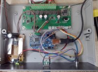
Another strange thing.
I use a 20V smps. When i power up the amplifier it draws 10V?
EDIT: i think the step down buck converter to the volume pot is causing trouble, i will remove it.


I use a 20V smps. When i power up the amplifier it draws 10V?
EDIT: i think the step down buck converter to the volume pot is causing trouble, i will remove it.
Last edited:
Why do people not use shielded cable inside their builds?I see all kinds of , IMHO, weird wiring protocols....
Just my 1 cent.
Kind regards,
Willem.
Just my 1 cent.
Kind regards,
Willem.
Guess it has to do with my OCD, like neath and shielded cabling, probably due to my background in PA- and studio gear.If it not is a problem with unshielded why bother?
Kind regards,
Willem.
He he 😉
this is an amplifier for my off grid
cabin with 12V solar panels it isnt that important

OCD is at home:

this is an amplifier for my off grid
cabin with 12V solar panels it isnt that important
OCD is at home:
As you have said earlier, it is time to strip it back or disconnect as much as possible and verify thye are working in isolation.
Your PSU at 10V is an obvious clue to something being amiss. As ever maybe worth going over the earthing strategy. The board is on isolated standoffs I vaguely remember from building the kit?
Your PSU at 10V is an obvious clue to something being amiss. As ever maybe worth going over the earthing strategy. The board is on isolated standoffs I vaguely remember from building the kit?
Holy crap, that's a nice cabin!He he 😉
this is an amplifier for my off grid
cabin with 12V solar panels it isnt that important
The motorized volumpot was the problem. Isolated it by using a 9V battery. Now the amplifier board gets 20V 🙂As you have said earlier, it is time to strip it back or disconnect as much as possible and verify thye are working in isolation.
Your PSU at 10V is an obvious clue to something being amiss. As ever maybe worth going over the earthing strategy. The board is on isolated standoffs I vaguely remember from building the kit?
The original standofs was a metal screw with a plastic tube.
Thx justanalogue.
These kind of rural cabins is not that expensive i Norway either. And the location and view is often much much better than in the established luxury cabin areas. But you have to carry water, du your business outside in a cold outhouse, empty the loo every second year and dig a big hole in the ground and put it there. Then i have a fuel aggregate to topfill the batteries in the very dark winter, a diesel oven, two fireovens, a small propane fridge, propan cooker……well you need to be Mcgyver, its a lot to do. Did i mention chopping wood? 🙂
These kind of rural cabins is not that expensive i Norway either. And the location and view is often much much better than in the established luxury cabin areas. But you have to carry water, du your business outside in a cold outhouse, empty the loo every second year and dig a big hole in the ground and put it there. Then i have a fuel aggregate to topfill the batteries in the very dark winter, a diesel oven, two fireovens, a small propane fridge, propan cooker……well you need to be Mcgyver, its a lot to do. Did i mention chopping wood? 🙂
- Home
- Vendor's Bazaar
- ZOUDIO AIO4CH: 4-channel amplifier with DSP and Bluetooth