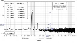
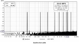
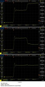
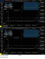
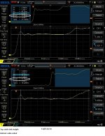
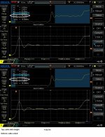
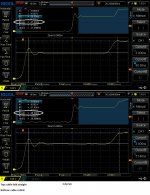
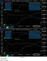
IMD dual tone test freq are 75Hz and 700Hz 4:1
IMD tests with amplifier outputing 0.45Vrms (50mW@4Ohm), with the 5inch FR speaker producing 80dB SPL/1m
Test on 5m long zip cables (2x0.5mm^2)
1 zip. Char imp:132 Ohm
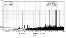
4 zip paralleled. Char imp:32 Ohm
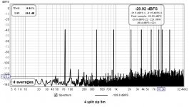
4 split zip (3inch spaced) paralleled. Char imp:300 Ohm
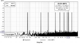
8 zip paralleled. Char imp:18 Ohm
(Char imp is TDR determined)
George
IMD tests with amplifier outputing 0.45Vrms (50mW@4Ohm), with the 5inch FR speaker producing 80dB SPL/1m
Test on 5m long zip cables (2x0.5mm^2)
1 zip. Char imp:132 Ohm
4 zip paralleled. Char imp:32 Ohm
4 split zip (3inch spaced) paralleled. Char imp:300 Ohm
8 zip paralleled. Char imp:18 Ohm
(Char imp is TDR determined)
George
Attachments
-
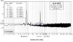 1 baseline (3cm cable to 5inch OB).jpg116.6 KB · Views: 235
 -
 9 test speaker.jpg126.5 KB · Views: 114
 -
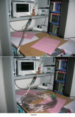
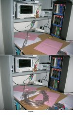
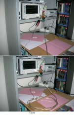
 7 IMD test setup.JPG523.3 KB · Views: 107
 -
 6 IMD baseline setup.JPG537.7 KB · Views: 109
 -
 5 8 zip paralleled 5m to 5inch OB.jpg109 KB · Views: 193
 -
 4 4 split zips 5m to 5inch OB.jpg116.4 KB · Views: 199
 -
 3 4 zip paralleled 5m to 5inch OB.jpg109.1 KB · Views: 183
 -
 2 1 zip 5m to 5inch OB.jpg109.3 KB · Views: 239
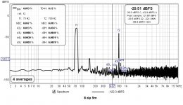
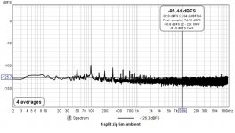
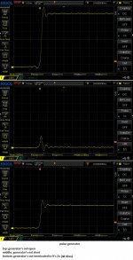
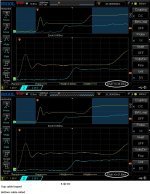
Multitone test (same test setup as with two tone IMD test above)
George
George
Attachments

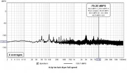
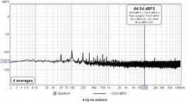
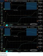
Noise pick-up test of those cables (part 1)
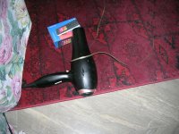
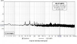
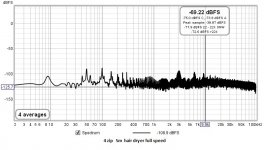
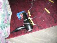
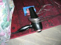
Ambient electr/magn noise and electr/magn noise from a main's powered hair drier in contact with the cables operating at half and full speed.
Same test setup as above, only soundcard and amp at idle (no excitation signal)
1 zip and
4 zip
George
Ambient electr/magn noise and electr/magn noise from a main's powered hair drier in contact with the cables operating at half and full speed.
Same test setup as above, only soundcard and amp at idle (no excitation signal)
1 zip and
4 zip
George
Attachments
-
 9.JPG659.8 KB · Views: 115
 -
 8.JPG663.4 KB · Views: 116
 -
 6 4 zips par hair dryer half speed.jpg104.5 KB · Views: 98
 -
 5 4 zips par hair dryer full speed.jpg104.4 KB · Views: 105
 -
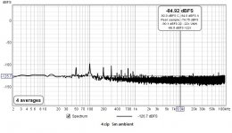 4 4 zips par ambient.jpg102.5 KB · Views: 96
 -
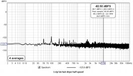 3 1 zip hair dryer half speed.jpg104.6 KB · Views: 106
 -
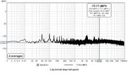 2 1 zip hair dryer full speed.jpg105 KB · Views: 122
 -
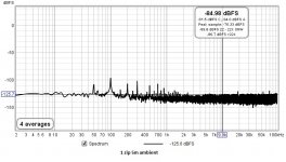 1 1 zip ambient.jpg103.2 KB · Views: 142
 -
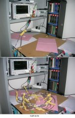
 IMD test and noise pick-up setup.JPG523.3 KB · Views: 102
Noise pick-up test of those cables (part 2)
Ambient electr/magn noise and electr/magn noise from a main's powered hair drier in contact with the cables operating at half and full speed.
4 zip and
8 zip
George
Ambient electr/magn noise and electr/magn noise from a main's powered hair drier in contact with the cables operating at half and full speed.
4 zip and
8 zip
George
Attachments
-
 10.JPG907.4 KB · Views: 137
 -
 9.JPG688.1 KB · Views: 108
 -
 8.JPG663.2 KB · Views: 92
 -
 7.JPG664.1 KB · Views: 100
 -
 6 8 zips par hair dryer half speed.jpg104.5 KB · Views: 99
 -
 5 8 zips par hair dryer full speed.jpg104.9 KB · Views: 95
 -
 4 8 zips par ambient.jpg103 KB · Views: 104
 -
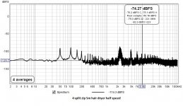 3 4 split zips hair dryer half speed.jpg106.5 KB · Views: 99
 -
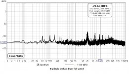 2 4 split zips hair dryer full speed.jpg106.6 KB · Views: 113
 -
 1 4 split zips ambient.jpg103.5 KB · Views: 129
Wonderful work George, thank you.
Looks like the 2nd of the 75hz is dependent on both the resistance of the loop and the inductance. I can see differences in the 150 hz level.
Of course, 50dB down vs 70dB down, is that even remotely audible for a first harmonic??
What is interesting is that when you split the zip, you got a 50 hz lobe. I don't know, you may have to invest in copper screening to envelope your listening area....😀
Your setup was great, there was no 50 hz evident until you split the zip.
I had a talk with the beam lattice physicist yesterday, detailing the t-line mismatch settling time. If they go for it, and it works, it will be the cheapest fast orbit correction system fix on the planet. And, she will get all the credit...😉
Of course, that is how it is. I have no complaints...
If they do it and it works, I will post the brief details here. total elaboration would have to wait till they publish..
John
Thanks John
The two tone IMD test doesn't show much.
The multitone test is a bit more reveiling.
The better on all those three tests seems to me to be the 8 paralleled zip chord.
George
The two tone IMD test doesn't show much.
The multitone test is a bit more reveiling.
The better on all those three tests seems to me to be the 8 paralleled zip chord.
George
Yes, the 8 seems to get the response much closer to no cable at all, bringing all the grass below -125 dB. But still, 85dB below multitone levels, not something we hear.Thanks John
The two tone IMD test doesn't show much.
The multitone test is a bit more reveiling.
The better on all those three tests seems to me to be the 8 paralleled zip chord.
George
Not sure if it's because the cable z (inductance component) or loop resistance. Splitting the 4 zip did give a very slight increase of grass height, but I think the 8 was mainly resistance.
So really nothing measured that would explain audibility.
Other than the audibility test I propose, the only way I can think of to test the varying impedance effect on settling time is difference testing. Either I/O nulling on the cable ends, or two speaker terminal voltages with one running 4 zip normal, other 4 zip split. I recall the Isolda guy did an end to end test, but he botched it by not using differential measurements so introduced a loop trap.
Given real world with speaker, I can't see how a null test could be done well, the null is probably not strong enough to capture interchannel delays at the 10 or so microsecond level. My fallback always seems to be the human discernment.
John
ps..as an aside, are hair dryers required to meet any radiated EMI standards? If so, I could see the cord as the worst offender, not the body of the unit. Any ground loop in the audio chain would just love that stuff..
Last edited:
I wouldn't bother...George's tests have shown......wait for it....How about test tones plus hair dryer. Any intermodulation effects?
zip.😉
jn
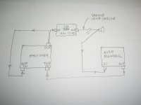
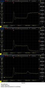
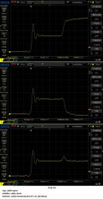
Before entering the REW impedance sweep subject (that's for tomorrow hopefully), here are the homebrew TDR screenshots for the zip cables under discussion.
George
George
Attachments
-
 8 zip 5m.jpg223.3 KB · Views: 108
 -
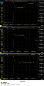 4 split zip 5m.jpg223.3 KB · Views: 120
 -
 4 zip 5m.jpg220.4 KB · Views: 117
 -
 1 zip 5m.jpg223.6 KB · Views: 132
 -
 pulse generator.jpg225.4 KB · Views: 128
 -
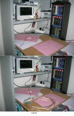
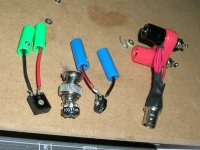 cable terminations.JPG637.1 KB · Views: 128
 -
 b.JPG605.8 KB · Views: 129
 -
 generator waveform.png31.7 KB · Views: 115
 -
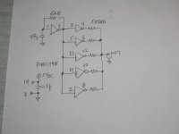 schematic.jpg538 KB · Views: 125
Nice. Considerably above and beyond, George.
It's really cool to see the zip cables actually acting like transmission lines. Many people don't think of zip as being capable of such.
Of course, it is always important to consider the time base involved. My t-line analysis of settling time is only valid for tens of microseconds at best, as the losses in the cable add up fast and kill the ideal analysis; real life is actually worse than what my settling time graphs show.
Excellent work George. I love it.
John
 Hi George,
With 5 meter cable, reflection is at ca 3Mhz.
The 36R and 300R termination that you found for resp. 4 zips and 4 unzips matches perfectly with the image in posting #104 at 3Mhz.
Well done for a lot of work.
Unfortunately the distortion figures do not reveal that much, despite all your extreme positive effort to find something.
If every difference we hear could be proven by measurements, we are not yet on the right trace.
The other possibility is that my brains are fooling me when I mean to hear clear and obvious differences between the zip and my LS cable 😀 😀
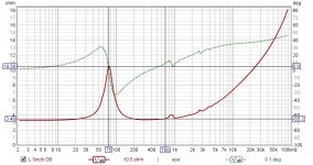
The only thing that took me by surprise so far is that the Zo of my cable matches the impedance of my speaker so closely.
But reflections at audio frequencies cannot be the cause of a supposedly improved sound, so the only thing left that I can think of is the storage and transfer of energy.
Hans
Last edited:
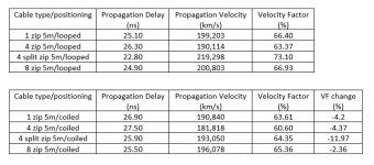
One more characteristic that can be measured by TDR on a cable is it’s propagation delay.
Then with it’s physical length known, the propagation velocity can be calculated, thus it’s velocity factor VF can be estimated.
I did all that it with the zips laid out straight and then coiled (to see how much VF changes by cable positioning)
George
Then with it’s physical length known, the propagation velocity can be calculated, thus it’s velocity factor VF can be estimated.
I did all that it with the zips laid out straight and then coiled (to see how much VF changes by cable positioning)
George
Attachments
-
 8 zip 5m.jpg222 KB · Views: 95
 -
 4 split zip 5m.jpg221 KB · Views: 96
 -
 4 zip 5m.jpg218 KB · Views: 106
 -
 1 zip 5m.jpg211.6 KB · Views: 177
 -
 8 zip 5m (1).jpg269.5 KB · Views: 177
 -
 4 split zip 5m (1).jpg275.5 KB · Views: 175
 -
 4 zip 5m (1).jpg276.6 KB · Views: 192
 -
 1 zip 5m (1).jpg277.5 KB · Views: 204
 -
 TDR single channel measurements.jpg78.2 KB · Views: 101
Then 😀 I found out that Rigol can measure time delay btn two traces without manually positioning cursors on the screen, thus providing more consistent readings.
So I connected cable’s far end to Rigol’s second channel input and did the whole exercise again, zips looped btn the two inputs and then coiled.
George
So I connected cable’s far end to Rigol’s second channel input and did the whole exercise again, zips looped btn the two inputs and then coiled.
George
Attachments
-
 8 zip 5m.jpg228.4 KB · Views: 90
 -
 4 split zip 5m.jpg227.4 KB · Views: 92
 -
 4 zip 5m.jpg223.8 KB · Views: 90
 -
 1 zip 5m.jpg205 KB · Views: 104
 -
 8 zip 5m looped-coiled.jpg260.3 KB · Views: 90
 -
 4 split zip 5m looped-coiled.jpg259.9 KB · Views: 89
 -
 4 zip 5m looped-coiled.jpg257.7 KB · Views: 99
 -
 1 zip 5m looped-coiled.jpg258.4 KB · Views: 123
 -
 TDR Dual channel measurement.jpg78 KB · Views: 91
I guess this has to be a dispersionless cable (phase velocity constant across frequency spectrum). Oliver Heaviside’s model for a distortionless TLs was the one in which R/L=G/Cso the only thing left that I can think of is the storage and transfer of energy.
We can read Heaviside (regarding the subject related to JN investigations but in modern terminology) in these two TI ANs.
John, I hope you find them interesting 🙂
https://www.ti.com/lit/an/snla026a/snla026a.pdf?ts=1621154470305
https://www.ti.com/lit/an/snla027b/snla027b.pdf?ts=1621096416749
George
>Edit. There is a third one
https://www.ti.com/lit/an/snla028/snla028.pdf?ts=1621307827097
Thanks.
Funny, an807...
Page 4, figure 1...I would have added "and beyond".😀
Page 8, right after eq 29.... "send more power". Gotta love it..
Page 11, figure 12..I haven't seen a lattice diagram in three decades..
For voltage source driver:
Page 15, figure 14..for RL>Ro, resonance..this is what happens when a speaker unloads such that it's impedance is very high.
For RL<Ro, note Vload has a settling time. This is the condition with generic speaker cables driving a speaker.
But because the mismatch at the load is so great with zip, the graphs go further out before the load has reached full power . (lots of "send more power messages).
Hans, the reflections ARE the mechanism for the cable building up it's stored energy. A low impedance load driven by a high impedance cable will be current starved until sufficient time and reflections have occurred. Because the buildup is dependent on reflections, and because the reflection coefficient is dependent on the load, variation of the load impedance with frequency will cause variation in how quickly the cable charges up (current wise) in order to deliver the current the amplifier wants the load to pull.
George, I had hoped that the high z line (300) would have shown increased distortion caused by flux dragging and asymmetric eddy modulation decoupled from the amp output by a large settling time, but such was not the case.
So the only way I can think of to discern temporal variance vs frequency is by ear..
jn
Note on the third TI-AN I added in my previous post.
https://www.ti.com/lit/an/snla028/snla028.pdf?ts=1621307827097
Although AN-808 is mostly about digital signal integrity (fast rise time binary signals), the content of the first nine pages is about continuous frequency spectrum starting at low frequencies, well within audio frequency range.
George
https://www.ti.com/lit/an/snla028/snla028.pdf?ts=1621307827097
Although AN-808 is mostly about digital signal integrity (fast rise time binary signals), the content of the first nine pages is about continuous frequency spectrum starting at low frequencies, well within audio frequency range.
George
Now is as good a time to mention it. AN808 page 9 figure 6 shows prop velocity vs frequency.
In my T-line analysis, I kept it simple by not including dispersion in the discussion. I always noted in the past that inclusion of R and G would ONLY SLOW DOWN the final analysis, making the settling time longer.
Figure 6 shows the prop velocity for a #22awg wire with 15.7 pf/ft. Note that at 1khz, the prop velocity is 1/6th of the ideal hf velocity. If you apply that factor to my settling time graph, the settling becomes much longer. A 2 ohm load gets to 80% in about 80 uSec, an 8 ohm load gets to 80% in about 15 uSec, a 20 ohm load in about 6 uSec.
jn
Hi George,
Nice measurements, but speed of light should have a comma instead of dot 😀
I mentioned ca. 3Mhz frequency for 1/4 wavelength with 5 meter cables, based on Cyril Bateman's paper with 2.5Mhz oscillation also using 5 meter cables.
However with 2e8 m/sec propagation speed in a cable, this should be 10Mhz.
I wonder how he could could get this 2.5 Mhz.
Am I doing something wrong ?
The other thing is that the used FRA impedance viewer unfortunately has more problems as thought. So now I have built my own Impedance viewer in Excel.
Images are not as sexy, but 100% correct.
So I will do a new Zo test for the Zip cable because the ones I made are not to be trusted.
Hans
Last edited:
but speed of light should have a comma instead of dot 😀
Absolutely correct, I’ll fix it (here we use dot in place of your comma and vice versa, I didn't noticed it, apologies)
Images are not as sexy, but 100% correct.
Correctness in sex ?

But if you would like to please (me) as well as to educate, you may embrace your new Zo graph in red or black lingerie
 😀
😀George
- Home
- General Interest
- Everything Else
- Zip cord for speaker test