As an aside, I researched belden triaxial cable, RG-59 belden P/N 88232.
Installing 45 kilometers of 50 ohm coax is probably a deal killer (I assume) for upper management.
It has two copper braid shields, an equivalent resistance per foot to #14 AWG, and from the dimensions on their site and assuming the FEP has a relative permittivity of 3, the characteristic impedance is close to 10 ohms between the shields. The OD if the inner conductor is .140 inches, the OD of the insulation is .188, the K I used is 3.
here is the calculator:
https://www.pasternack.com/t-calculator-coax-cutoff.aspx
Should anyone ever decide to try this cable, I ABSOLUTELY recommend the use of a zobel at the speaker. otherwise, some people may toast their amplifier.
John
If the cables are the same length the effect will be inaudible for any sound down the middle, same delays to both speakers, no image shift. So to exaggerate the effect use different lengths and listen for localization of sounds between center and a speaker. And use something easy to locate like a solo mono drum with lots of content in the freq. range of interest.
Last edited:
Electric conductivity is low on all SSs.It is also possible that most of it is being caused by eddy current effects of the magfield trying to go through a 1.5mm wall of conductive material, stainless IIRC.
Magnetic permeability is also very low, except for a few (302, 304) that when cold worked, mu can increase 10 fold.
George
Interesting observation.As an aside, I researched belden triaxial cable, RG-59 belden P/N 88232.
It has two copper braid shields, an equivalent resistance per foot to #14 AWG, and from the dimensions on their site and assuming the FEP has a relative permittivity of 3, the characteristic impedance is close to 10 ohms between the shields.
John
Any idea at what frequency the knee point is located as from where char imp goes up when going down in frequency ?
May be the ideal victim for the next series of tests.
Hans
No idea. But the calculator pops out the L and C per foot, and it's 2.6 ohms per kilo foot per conductor.
I'm sure the shield to shield insulation is solid FEP as opposed to the core foam used for prop velocity.
If the higher ups and physicists (actually, the higher ups are physicists)deem it worthwhile, I'll get a few hundred feet in for experiments and analysis. Not sure who at work has a VNA, but someone has to have one. Or, I'd probably have to send some to a person I know who has one.😉
Jn
If the cables are the same length the effect will be inaudible for any sound down the middle, same delays to both speakers, no image shift. So to exaggerate the effect use different lengths and listen for localization of sounds between center and a speaker. And use something easy to locate like a solo mono drum with lots of content in the freq. range of interest.
A reasonable proposal. I decided to go with the 4 zips split and not, as I did not want to include the confounder of loop resistance. Granted, it's low anyway but some would still claim damping factor as a possibility.
Jn
Last edited:
Eww. Hadn't considered availability.
I just assumed that if it is on their catalog it is available.
For me, if the higher ups go for it, we'll probably just buy 10 to 20 thousand feet. I assume even Belden wouldn't deny us the material.
In the past, I went to order something and the sales guy kinds hinted we couldn't afford it, there was an NRE, there was a minimum quantity of ten thousand feet..yada yada yada.
I slowly explained that we already assumed as much...
John
I’ve ordered 10 feet 9222 triaxial, just to get some feeling about the potential.
Will arrive tuesday.
Hans
Will arrive tuesday.
Hans
JN, I hope that you realize that RG-59 and belden P/N 88232 are 75 ohm impedance and not 50 ohm. RG-58 is 50 ohm.
From post 141 you mentioned 50 ohm coax.
From post 141 you mentioned 50 ohm coax.
Last edited:
Ah, thank you, you are keeping me on my toes....😉
I will explain better.
The wire being used is I believe a 1kV rated twisted pair, so the insulation is fairly thick. This brings the impedance up, I am guessing roughly 150 ohms.
You are correct, I did mention 50 ohm coax. My intent at first was to use 5 paralleled 50 ohm coaxial cables with a effective impedance of 10 ohms. That would drop any wire settling time into a 1 or 2 ohm load (resistive) down into the single digit microsecond range.
900 runs of coax is a lot. So I researched triax, the intent is to use the two shield braids as the coaxial run. The inner core wire will not be used to carry current, it probably won't even be connected. It's the outer two braids that have an impedance of 10 ohms between them.
But thanks for picking that up. If I had been relying on the core impedance, I'd have been 50% off the mark...and totally sunk..
But now you have me thinking...If I use the inner shield as ground reference, the outer as the hot (+/- 20 volts), then I could use that 75 ohm core wire as a voltage readback from the magnet...hmmm. I'll be thinking about whether that buys me anything..
Thanks again,
John
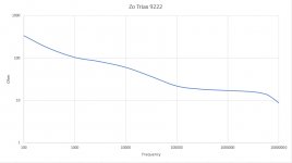
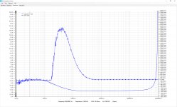
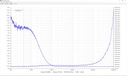
Here are resp. the Char. Imp, the Capacity open ended and Inductance with end shorted for a 3 meter 9222 Belden Triax cable measured between the two outer shielding layers.
Doesn't look like the ideal speaker connection to me in this form.
Hans
.
Doesn't look like the ideal speaker connection to me in this form.
Hans
.
Attachments
I'm not exactly sure what an ideal speaker cable would look like in that form.
John
Oh, and thank you for that test result.
John
Oh, and thank you for that test result.
John,
Neither did I, because so far I was never interested in the so called superior technical aspects of a speaker cable and only trusted my ears.
But after having recently measured my own LS cable, I was astonished how close the Char. Impedance matched the impedance of my speakers.
Perhaps I fool myself, but to my ears the sound of my cable is far superior to zip cord or whatever other simple type of connection.
So it could be that impedance matching is much more important than I ever thought.
In that case this triax cable does not have the right impedance form. 😀 😀
Hans
As mentioned already to George, I found an error in the capacity calculation of the used software.
Will redo the measurements once corrected.
Hans
Will redo the measurements once corrected.
Hans
Luckily I can confirm that the calculations I used for finding the Char. Impedance were correct after all because I used the impedance measurement of the used FRA Imp Viewer.
However the images showing capacitances are wrong most of the time, because of a simplified calculation that may give erroneous results in some cases.
But the impedance calculations are fully correct, so all the images relating to impedance and Char Impedance in this thread still hold.
Pfffff.....
Hans
Still frustrating is that I couldn’t convince the author of the program of his wrong calculation.
When Z = A + JB and you want to calculate the capacitance, then
1/jwC= A + jB
His aproach is in that case to say jwC = 1/jB or C = 1/wB
Because j are in the numerator and in the denominator, this is wrong.
Correct is: jwC = Im( 1/(A + jB)
Solving this gives jwC = jB/(A^2 + B^2)
or C = [B/(A^2 + B^2)] / w
When A is very small, both formulas give equal results with 1/Bw.
So sometimes the result is o.k. but most of the time it’s not.
Hans
- Home
- General Interest
- Everything Else
- Zip cord for speaker test