The test design George shows in #187 is not optimal for measuring a phase shift of an open cable. It is designed to measure the settling time caused by a load which has a characteristic impedance different from that of the wires.
When the line and load matches, the current will settle in zero time at the source. When the load impedance is below the line impedance, the line will take a finite time to achieve the current demanded by the load in response to the source voltage. This finite time is a consequence of the transit time within the cable conspiring with the reflection coefficient of the load.
The entire scope of the test is to show how a varying load impedance will cause a varying delay in current settling. I designed it so that there was no loop in the ground to the scope. Also, to maintain the reflection coefficient of the source, the CVR MUST be an extremely low inductance and very low resistance. Hence the CVR must be designed carefully.
My test design can also be driven with variable sine, and the phase shift of the current caused by the load mismatched to the line can be measured as well. However, trying to elicit phase shifts in the audio band where the temporal shift is in the 10 uSec range is not a trivial exercise. That is why my first choice is a voltage step signal, and watch the current rise to the load defined current.
john
Last edited:
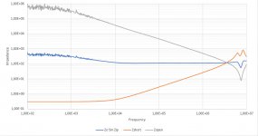
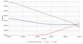
This is what I get with a single 5meter zipped cable.
Quite a bit easier to measure than unzipped cable.
This measurement was done with coax cables instead of probes with a 100R reference resistor.
Difference is a somewhat better HF part, but a noisier LF part.
Hans
P.S. @ George. Could you repeat your measurewment with a 100R CVR? That enables to compare results.
.
Attachments
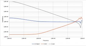
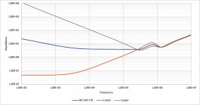
After having finally found the best set-up to measure cable's Zo, and after having solved the trouble with the previous faulty software, I have repeated all test and put them all together in one posting.
Recording was done from 100Hz to 10Mhz with 150 points per decade, 750 in total to get the most accurate results.
A 100R very low induction resistor was used as a reference.
But in those cases where Zopen was very high at 100Hz, a higher value was used between 1K and 10K.
Cables were 5 meter long, except the 9222 Triax and the MH-770 that were 3 meters.
Hans
.
Attachments
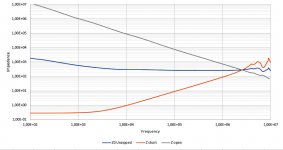

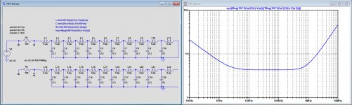
I was just playing around with LTSpice, trying to emulate the measured MIT cable.
Starting point was the measured 2.2uH open ended and 120nF shorted cable.
These values were divided over 10 segments as folows: L=0.2uH + Rs=3mR, C=12nF + Ls=2uH + Rs=25R.
Simulated Zo result came already remarkably close to the original recorded Zo curve except for the (meaningless?) bubble around 800Khz.
I'm almost tempted to construct this to find out how it compares sound wise to the real one.
Hans
.
Attachments
Could somebody solve the mistery why Cyril Batememan had 1/4 wavelength oscillations at 2.5 Mhz with 5 meter cable that were ruining his Amps.
With 2e8 m/sec cable propagation, 5 meter takes 5m/2e8 = 25 nsec, giving 1/(4*25nsec) = 10Mhz instead of 2.5Mhz ??
Question is because: do whe have to look for Zo at 2.5 Mhz or at 10Mhz to prevent the mismatch between speaker with 5 m cable blowing your Amp to pieces because of a reflection coefficient close to one.
If so, the simple solution is a Zobel network at the speakers end of the cable.
Hans
I think I can give the answer to the above question.
When reflection coefficient is close to 1, reflections of opposite polarity are taking place even before 1/4 WL, but phase shifted and with lower amplitude.
Obviously these smaller non 180 degrees reflections are enough to trigger the oscillations at a lower 2.5Mhz frequency, in fact in this case already at 1/16 WL.
For a 2.5meter cable this would then be at 5Mhz.
So Zo and Zl should be considered from 2.5 to 5Mhz with rho=(Zl-Zo)/(Zl+Z0), with Zl being the LS impedance at the corresponding frequency and rho the reflection coefficient.
Rho should be close to zero to prevent any such reflection caused oscillations, if needed by placing a Zobel network.
Hans
Correction on silly error in the above posting: a returning reflection at the Amp’s output for a 1/4WL cable length with unterminated LS end is of course not 180 degrees but exactly in phase.
Hans
Hans
I decided to take the dive by trying to emulate the MIT MH-770.
I bought 4mm^2 zip cord, that has the same 100R char imp as the 0.5mm^2 version.
But Resr for a 2.5m cable is now 30mR, needed to get a low Zo below 1Khz.
I can use the cable's inductance , divided over 4 segments of 0.38uH each in combination with three 30nF Caps, giving a Zo=sqrt(4x0.38u/3x30n)=4.1R.
In series with the caps there are resistors and additional inductors needed to get the whole thing as close to the MH-770 as possible.
Having achieved that, I will do the following:
1) Listen to the two speakers driven through 2x MH-770 cables from one amp.
2) One MH-770 + one emulated MH-770 cable based on 4mm^2 zip plus caps etc.
3) One MH-770 + one unmodified 4mm^2 zip.
Although results will be subjective, I will try to listen as unbiased as possible.
Hans
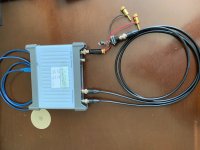
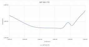
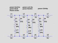
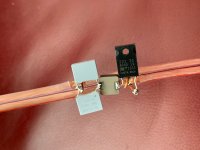
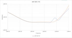
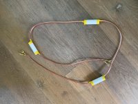
I managed to realize the impedance curve I was aiming for to emulate the MIT MH-770 LS Cable.
I used a 2 x 4mm^2 zip cable with Zo = 100R and added RLC networks, based on measurements of the Zip cable showing 1.5uH and 150pF for 2.5 meter cable.
See images below for the network, a picture of one of the three RLC networks that where added and the Zo curve in orange projected on the MIT MH-77- curve.
Auditioning will be done later this week.
Hans
.
Attachments
The MIT stuff is interesting. Many years ago I helped build one of Bruce Brisson's "magic boxes" with the various loading coils individually switchable. He said it should work as an equalizer. Well, if you wished real hard you could hear the effect but it seemed that the different series coils were all shorted in fact. The wire itself should be somewhat inductive but again twisted wire conductors of different gauge wrapped around each other in the hope that different frequencies would follow different conductors. I could never find a test to validate that claim or even see an effect.
I'm ready to duplicate these efforts to see what I can see. I could also try TDR tests but I'm not sure if the effects would show. Maybe a TDR pulse and look at the current at the far end with a current probe? I'm naively thinking it would show the slow rise of the current with a mismatch? What source impedance for the TDR pulse?
I'm ready to duplicate these efforts to see what I can see. I could also try TDR tests but I'm not sure if the effects would show. Maybe a TDR pulse and look at the current at the far end with a current probe? I'm naively thinking it would show the slow rise of the current with a mismatch? What source impedance for the TDR pulse?
Hi Demian,
When looking at the many patents that Bruce Brisson has filed, it starts with rather chaotic theories and implementations, more and more diverging eventually to a straightforward solution like the one that I have chosen with RLC networks between the conductors.
Since I own this MH-770 version, I’m curious to find out how and if it differs from my emulation.
As a matter of fact, what do you mean with a TDR and what can be done with it?
Hans
TDR = Time domain refletometry. Its a time based analog of the frequency based measurements you have been making. Its possible to transform from one to the other. However I don't have the math skills or software to do the transform. Its a feature of some VNA's.
My hope would be able to see the energy fill JN has discussed. It should also be possible to see all this in the motion of the transducer. I have a gadget for that as well.
As to experimental setup. Swept source or pulse generator- what source Z? should all the voltage and current measurements be differential? Current probe or current shunt + voltage probe? I also have a low frequency VSWR bridge. Should i fire that up? (need to figure out how- its active.)
I may have some MIT cables in the pile. I'll be checking.
When You have some MIT LS cables, preferably the more exotic, it would be nice if you could make the same Zo calculation as I did from the VNA's open and shorted recording.
But apart from all possible measurements, I'm curious to find out whether there are any audible differences between the three I have at my disposal.
Between the MH-770 and the 2 x 0.5^2 Zip there were clear differences to be heard for my ears and I don't have golden ears or anything near.
Hans
P.S. I'm sure Syn08 is scratching his head for so much ignorance 😀 😀
So here are the results of my listening tests taken with ESL63’s connected to a 100W@8R class A amp. Only one channel playing, source set to mono.
All cables having the same length of 2.5 meter.
1) zip 0.5mm^2 and zip 4mm^2, both with Zo = 100R.
No noticeable difference between them, but sound without depth and width, flat and uninspiring.
2) MIT MH-770. A very 3 dimensional sound giving a “you are there” experience.
Sometimes possibly a tiny bit too wooly and warm, but very agreable to listen at.
3) My emulation. Also very 3 dimensional, less wooly and warm with better articulation of voices, but sometimes a bit too analytical.
Since I used cheap caps for this experiment, I will try to replace them by polystyrene versions and see what that brings, but the conclusion is that this experiment showed that you can clearly improve the sound of a simple zip cord quite a bit, at least for an audio set as I have.
You don’t need golden ears, everybody can hear it, difference is not subtle.
For below $30,- you can make a high end cable set.
The 4mm^2 OFC cable from Amazon costed €28,- for 15 meters, so less then €10.- for a 2.5 meter set!
Will tell after having changed the caps to higher quality versions, what the difference is, if any.
Hans
"For below $30,- you can make a high end cable set."
Hopefully nobody accuses you of conspiracy, nor of lunacy.
Hopefully nobody accuses you of conspiracy, nor of lunacy.
Hi Mark,
Conspiracy against what or whom ?
And I mentioned earlier in this thread that some people will probably declare me to be mad, so lunacy is fine.
I just reported my own experience and don’t put this as general wisdom.
Everybody should make his or her open minded judgement.
Hans
Conspiracy against what or whom ?
And I mentioned earlier in this thread that some people will probably declare me to be mad, so lunacy is fine.
I just reported my own experience and don’t put this as general wisdom.
Everybody should make his or her open minded judgement.
Hans
Demian,
Did you already have the opportunity to go trough your cable pile in search of MIT LS cables.
If so, i would be interested to get the type numbers to see whether further investigation makes sense.
Hans
Did you already have the opportunity to go trough your cable pile in search of MIT LS cables.
If so, i would be interested to get the type numbers to see whether further investigation makes sense.
Hans
- Home
- General Interest
- Everything Else
- Zip cord for speaker test