Okay, this is from my email correspondence with Brian Sowter in 2004:my Sowters
Suggested wire colours?
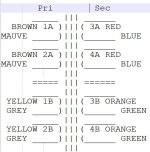
Pri Sec
_____ ||| ______
BROWN 1A )|||( 3A RED
MAUVE _____)|||(______ BLUE
_____ ||| ______
BROWN 2A )|||( 4A RED
MAUVE _____)|||(______ BLUE
|||
===== ||| ======
_____ ||| ______
YELLOW 1B )|||( 3B ORANGE
GREY _____)|||(______ GREEN
_____ ||| ______
YELLOW 2B )|||( 4B ORANGE
GREY _____)|||(______ GREEN
|||
Sorry, it's ASCII art and will need reformatting to line things up.
I don't know if Sowter turned the bobbin round for the second section, or just carried on winding.

Oops. Sorry, my introductory sentence was meant for context and it threw you off the track.I have never had any of the big output transformers from Sowter.
What I was trying to ask was/is, whilst winding an aperture of quad-filar OPT, whether or not you recommend allowing the four wires to flip once they reach the end or the opposite which would be to keep them from flipping? (This is not so easy to ask. I shall clarify.)
In other words #1, assume that the winding starts on the left and moves rightward, would the right-most wire always stay on the right of the other three wires even after reaching the right-most end of the bobbin and working back toward the left?
In other words #2, is the wire that leads toward the right the same wire that leads toward the left; or instead does the wire that leads toward the right become the wire that lags the other three on the way back toward the left?
Thanks.
P.S. I fixed your drawing and attached it below.
Attachments
Ah, okay!whether or not you recommend allowing the four wires to flip once they reach the end
Yes, I would flip them - that way one should have less of a void as four wires side-by-side is 4.something mm which is a big gap in a 25mm aperture.
I need to get my four heavy-duty wire tensioners setup. I plan on having them vertical one above the other and a wire-guide that toggles between left and right leading for the group of four wires.
New amplifier project progress:
Finished the metalwork (i.e. making holes) for the power-supplies for the new power-amplifiers, and mounted all the major components.
The Parsonage c-core transformers were also purchased in 2009; their secondary is specified at 32V 10A RMS.
Not yet wired up, and I have to assemble the current-regulators (which go on the heat sinks).
The aluminium diecast boxes and heat sinks are repurposed (i.e. saved from WEEE) so have the odd extra hole in them.
This is serious and probably escaped from a lab at Oxford.
Absolutely love this work, and especially how open @Susan_Parker has been with her knowledge. Even though I'll generally be doing the Neurochrome thing (and eschewing power valves for environmental reasons) I'm 100% building one of these 🙂
If there were a build guide, I would give it a go too. But without one, I would be too afraid of opening a black hole.
I'm gonna wing it 🙂 My spidey sense says that it's straightforward and pretty layout insensitive (but I definitely can be wrong). I think that the key is getting the output transformers correct. I'm toying with winding my own, but may bite the bullet, save some time and get the Sowters.
I have a dead power amp chassis to build the amp proper into, and likely have something to put the power supply in as well, so have a decent starting point. I know it's recommended to have the amps next to their respective speakers, but I'm hoping I can mount these a short distance away and make up for it with better/bigger cables.
I have a dead power amp chassis to build the amp proper into, and likely have something to put the power supply in as well, so have a decent starting point. I know it's recommended to have the amps next to their respective speakers, but I'm hoping I can mount these a short distance away and make up for it with better/bigger cables.
What would be considered as the needed information for a build guide?If there were a build guide, I would give it a go too.
For the power-stage: the simplest SE version is to re-stack the output-transformer's EI-120 laminations to add a gap of c. 0.6mm to 1.0mm (depending on biasing current), then have the two primaries in parallel (as opposed to series in the PP) to ground but still use two MOSFETS with the input transformer reconfigured so both secondaries are in-phase.Could you tell me more about the SE version?
Bias the mosfets so they are running at about 1.5A to 2.0A each, see these wire tables for wire-diameter versus max-currents:
https://www.remingtonindustries.com/content/Remington Copper and Magnet Wire Data Chart.pdf
Note large heatsinks are required for this - power dissipation will also obviously also depend on B+ supply voltage.
What would be considered as the needed information for a build guide?
That's a good question!
The schematic in the first post is simple enough and most would say "What could possibly go wrong?".
I guess a guide would include:
- Detailed characteristics of the parts needed and maybe where to source them.
- Steps to verify the parts.
- Order of assembly.
- Safety precautions and verification of assembly.
In retrospect, it is quite possible I make a big deal out of nothing.
I also guess gathering the right parts is the biggest challenge.
Yes, this I can understand and relate to.I also guess gathering the right parts is the biggest challenge.
I spend many hours looking at things I might be able to use for cases, and hopefully doom-scrolling through eBay listings for BIG heatsinks!
I believe that the circuits are at a level of similar complexity to building linear regulated power-supplies.
Knowing which parts to buy is something I will try to expand on.
Thanks.
Today has seen some progress on the next part of the new system; started making the holes for the new preamp's rear panel - in this case two rows of XLR connectors for the inputs. As it's a 1mm steel panel I can use a punch to open out the main connector body holes.
My Emco F1 CNC milling machine only has a 200mm x 100mm working envelope, so I will have to shift the panel left and then right to get in the holes for the other connectors and associated parts.


My Emco F1 CNC milling machine only has a 200mm x 100mm working envelope, so I will have to shift the panel left and then right to get in the holes for the other connectors and associated parts.
I first used a center-drill to spot all the hole positions, then drilled out the holes on a seperate pass.
...
This tracking is because I am using the MOSFETs as Gate Followers, not as amplifiers. Therefore the transformer arms follow the the gate input voltage minus the MOSFET bias level - the actual gain is a little less than unity.
So since both MOSFETS are activly working the whole time I guess it's Class A.
Thank you for your interest.
Best wishes,
Susan.
This is my first post here after browsing the thread many times.
IMHO Susan's amplifier topology is one of the most brilliant because of its simplicity and it's possibly the ultimate approach to 'straight wire with gain'.
That said, I was wondering if GAN FETs could be used as a Gate Follower.
Example:
Attachments
Last edited:
Hi, welcome 🙂I was wondering if GAN FETs could be used as a Gate Follower.
Thank you.
I don't see why GAN FETs wouldn't work as followers, however whether they give any advantage is another matter (the datasheet load-line graph is not very forthcoming to how they will work in practise. From what I have read I suspect that they will make very good VHF oscillators.
I would strongly recommend anyone starting out with my transformer topology to test a basic power stage with "cheep as chips" MOSFETS such as the IRF150 parts which is what I used in my Zeus35 amps (which are still in use unmodified in any way since I built them in 1995).
... then try out other parts with the same bias-current, which gives a baseline setup to compare with.
Basic note: ALWAYS include the gate protection Zener diodes - they are NOT optional!!!
Thank you for the swift and insightful reply.
Another question:
Is it possible to use an output transformer that can be configured for low output impedance or high level output by connecting the twin secondary windings in parallel or series?
Another question:
Is it possible to use an output transformer that can be configured for low output impedance or high level output by connecting the twin secondary windings in parallel or series?
I'm not Susan (and I may well be mistaken, I'm new to this) but isn't that part of the feature set of the Sowter 9840?
There's talk earlier of going hexfilar for more flexibility. Here's a post with some numbers: https://www.diyaudio.com/community/...pedance-amplifiers.42259/page-98#post-7909457
There's talk earlier of going hexfilar for more flexibility. Here's a post with some numbers: https://www.diyaudio.com/community/...pedance-amplifiers.42259/page-98#post-7909457
- Home
- Amplifiers
- Solid State
- Zero Feedback Impedance Amplifiers