I will need to do a proper winding calculation - the aim is to have the primaries always tightly coupled in bi- or quad-filar grouping. In a dual chamber bobbin of an EI-120 core winding a hex-filar is going to be very-fiddly. Winding for a C-core might be a bit easier as the bobbins are longer.Footnote 1:
I'm left confused because I thought I only needed four more windings in total, two more for the primary and two more for the secondary; a total of 12 windings. Also I was / am assuming the dual-bobbin standard configuration. Across two bobbins, four extra windings would only amount to one extra bi-filar section needed per bobbin.
I will have to do the proper calcs to confirm.
Nice.That should work, I also have a couple of 10k CT: 600R Edcors that I intend to try as step up/phase splitters.
The 25-70Hz range should be quite forgiving for cheap transformers.
As an alternative to get properly balanced mains transformers to use in reverse as input for bass below 100Hz then one can use this type of Flat Pack transformer:
https://www.mouser.fi/ProductDetail/Triad-Magnetics/FP24-1000?qs=Yx4IQMNd5u5fz6lHd7mh8A==
This has the advantage of filtering HF above c. 1kHz - as the side-by-side chambers don't couple the higher frequencies.
... okay @charliemb , some notebook doodling later:I will need to do a proper winding calculation -
To get 3:1 I had in mind to start with 2:1 and adds some more turns on the primary... not sure if this is ideal as the output resistance is almost the same as with 2:1 config.
EI-120 dual chamber has 25mm x 15mm winding aperture per side; I am assuming however for practicalities one is only going to get 12 layers in because of bulging across the windings.
Currently that gives 12 layers of quad-filar windings at 6 turns per layer, which is 72 turns per wire per side.
Reducing this to 10 layers of quad-filar then 2 layers of bifilar as a separate section reduces the quad-filar wires to 60 turns and adds 24 turns bi-filar per side.
P+
24 |||
24 |||
60 ||| 60
60 ||| 60
GND
60 ||| 60
60 ||| 60
24 |||
24 |||
P-
Cross couple the two secondary sides so that each series section winding is made from one winding from each chamber as with 2:1 setup.
?
I don't want to get in the way of the winding calculation discussion, but I'm curious what the reason would be for partially hand winding the output transformer? I simply don't know but curious (I may be winding my own). All of this is cool stuff!
Now you are making me think!... okay @charliemb , some notebook doodling later:
...I'll be back.
In the meantime, I understand or assume:To get 3:1 I had in mind to start with 2:1 and adds some more turns on the primary... not sure if this is ideal as the output resistance is almost the same as with 2:1 config.
EI-120 dual chamber has 25mm x 15mm winding aperture per side; I am assuming however for practicalities one is only going to get 12 layers in because of bulging across the windings.
Currently that gives 12 layers of quad-filar windings at 6 turns per layer, which is 72 turns per wire per side.
Reducing this to 10 layers of quad-filar then 2 layers of bifilar as a separate section reduces the quad-filar wires to 60 turns and adds 24 turns bi-filar per side.
- "side" means one side of the dual-chamber bobbin;
- "aperture" means the entire volumetric space inside each side, wherein the aperture has a width of 25mm and enough room for layers of 15mm;
- "layer" means one row of windings per side of the bobbin wherein the quad-filar section yields 6 turns per layer and wherein the bi-filar section yields 12 turns per layer;
- sections comprise layers of windings of the full width of each aperture, and there are only two sections per side, one section of quad-filer layers (10) and a second section of bi-filer layers (2) wound directly on top (or underneath) of the quad-filar section;
- all bi-filar windings remain on the primary side, four separate coils, and no new coils are added on the secondary;
- the new coils can't be placed in parallel on any of the secondary coils because the EMFs don't match with the EMFs generated by the 60 turn coils (as 24 != 60);
- The four 60-turn secondaries are connected 2:1, meaning two in parallel placed in series with the other two in parallel, and yes the paralleled coils can and should be cross coupled across bobbins.
Thanks
Dada dum de dum!...I'll be back.
Yes, all correct.In the meantime, I understand or assume:
I placed the additional bi-filar windings on the outside as that makes the DC resistance of the secondaries slightly smaller (maybe 5%?), in addition to the decrease from the reduction in the number of turns, compared to having the bi-filar layers first.
General note: Because of the use of a dual chamber bobbin, all winding sections have to be in multiples of 2 layers as the start and stop have to be on the outside.
The line-driver and power-stage output transformers are completly wound by hand by preference - from experience commercial machine winding bi-filar and quad-filar is not capable of putting down the layers without crossovers in the winding process.but I'm curious what the reason would be for partially hand winding the output transformer?
In my case I use my lathe to hold the bobbin on a plate and hand crank the spindle to turn, see pic.

Susan, if I may? Something like this Triode-PNP hybrid follower? The distortion depends mostly on triode. The simulation flatters maybe, but still. . Output is 'low enough' for a transformer.Nope, BJT transistors by themselves are not more suitable.
I use a Triode-BJT hybrid follower in some of my variations, for example line-drivers as can be seen in the pics in my previous post:
https://www.diyaudio.com/community/threads/zero-feedback-impedance-amplifiers.42259/post-7899562
[but] Not needed in my topology...
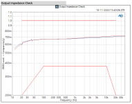
Impedance is fairly constant. [Made with 18042 as a test project for ETF'23; requirement was loading to a 600Ω output]. ECC82 is slightly different. ECC83 is great too. Just compare in vivo.
I am currently using such a stage without transformer : as a buffer after my 50k potmeter. The impulse and low level field presentation are astonishing of this hybrid. The input is self-biassing: the base current, ! Every small change in the coupling cap can be appreciated.
Attachments
Nope.Something like this Triode-PNP hybrid follower?
Fine to see your circuit simulations, but it is not my transformer/follower/transformer topology - see schematic and pic.
Tube is 7N7, Loktal version of 6SN7, BJT is 2SC5200.
Heaters powered by a PTN78060WAD non-Isolated DC/DC Converter with slow-start circuit.
B+ is +24V from a separate AC/DC supply.
Input-transformer is Hammond 124B, output-transformer is EI-96 quad-filar wound 0.8mm magnet-wire.
Schematic of Bipolar-Triode Hybrid line-driver
Inside view of the Bipolar-Triode Hybrid line-driver, in daily use as part of our 5.1 setup.
Rear view of the Bipolar-Triode Hybrid line-driver, in daily use as part of our 5.1 setup.
Nice balanced base-current concept. Does it require matched combo's? . . .
Then - Just an old thought: if the base current would be different, then on an ECC82 (version) , a deliberate slight imbalance of the two heater sections would be able to balance that again (Wireless World tip from the sixties).
Then - Just an old thought: if the base current would be different, then on an ECC82 (version) , a deliberate slight imbalance of the two heater sections would be able to balance that again (Wireless World tip from the sixties).
Thanks.... a deliberate slight imbalance of the two heater sections would be able to balance that again...
Yes, I am trying out some ECC99s with this in mind for the power stage.
https://www.jj-electronic.com/en/ecc99
I suspect however this may affect the transfer curves and thus the even-harmonics; more testing (and time to do testing) needed.
This is my current test-setup with a 7N7...
Yes, but one would need to bias the SITs as an additional circuit; so one then needs a matched pair and a third one to temp/co track the bias - as I do in my standard MOSFET configuration. If you have a stash, then great. Not sure where to buy any in sensible numbers e.g. 30+ to get matched pairs?Can SITs be made to work in the power stage?
I use Depletion Mode devices that auto-bias through the DC resistance of the windings, makes for simplicity and the input transformer is hard connected to the 0V rail (so one less potential source of noise/distortion).
Just as you wrote this a small inventory of matched SITs has come up in the swap meep, at attractive prices…
Nice! 🙂Just as you wrote this a small inventory of matched SITs has come up in the swap meep, at attractive prices…
I'm back. Regarding the 3:1 ponder and the prototype proposed here:Dada dum de dum!
Here is my analysis with estimates.... okay @charliemb , some notebook doodling later:
To get 3:1 I had in mind to start with 2:1 and adds some more turns on the primary... not sure if this is ideal as the output resistance is almost the same as with 2:1 config.
EI-120 dual chamber has 25mm x 15mm winding aperture per side; I am assuming however for practicalities one is only going to get 12 layers in because of bulging across the windings.
Currently that gives 12 layers of quad-filar windings at 6 turns per layer, which is 72 turns per wire per side.
Reducing this to 10 layers of quad-filar then 2 layers of bifilar as a separate section reduces the quad-filar wires to 60 turns and adds 24 turns bi-filar per side.
P+
24 |||
24 |||
60 ||| 60
60 ||| 60
GND
60 ||| 60
60 ||| 60
24 |||
24 |||
P-
Cross couple the two secondary sides so that each series section winding is made from one winding from each chamber as with 2:1 setup.
?
| 4:1 Standard Sowter 9840 OPT | 2:1 Standard Sowter 9840 OPT | 3:1 Hexa-filar wound | 3:1 Extra primary windings, Standard 2:1 output wiring. As proposed in the above post. | |
| Total output impedance | 0.257 Ω | 1.03 Ω | 0.456 Ω | 0.62 Ω |
| Damping factor | 31.2 (8Ω) 15.6 (4Ω) | 7.8 (8Ω) 3.9 (4Ω) | 17.54 (8Ω) 8.77 (4Ω) | 12.82 (8Ω) 6.41 (4Ω) |
| Average power output (best-case for 48 V DC supply) | 33.8 Watts into 8Ω 63.6 Watts into 4Ω | 113.1 Watts into 8Ω 182.4 into 4Ω | 57.3 Watts into 8Ω 103.1 Watts into 4Ω | 63.2 Watts into 8Ω 110 Watts into 4Ω |
| Turns ratio | 4:1 | 2:1 | 3:1 | 2.8:1 |
| Impedance ratio | 16:1 | 4:1 | 9:1 | 7.84:1 |
| Secondary winding configuration | Four in parallel, none in series | Two in parallel, two of those in series | Three in parallel, two of those in series | Like 2:1, Two in parallel, two of those in series |
| Relative distortion levels | Lowest | Higher | In between, probably | In between, probably |
| Bias current commentary for a given idle dissipation | Tends to stay in Class A the longest, but high rail voltage requirements limit bias current. Potentially not the best compromise but offers the best damping factor. | Tends to move into Class A/B the quickest due to highest primary currents. | Could tend to stay in class A comparably to 4:1 after increasing the bias current and lowering the rail voltage accordingly for the same power output. - Or, a higher power output can be chosen and move into class AB a little sooner. - Potentially closer to optimal but can only be considered if the damping factor is acceptable. | Ditto, as with 3:1. |
For the hexa-filar wound case, an assumption was made that more coils compensates for fewer turns per coil in order to fit within an EI-120. That is, the primary-side resistance is the same as for a Sowter 2940.
Outstanding, huge thanks for this detailed report. 🙂Here is my analysis with estimates.
One thing to note on distortion (from measurements I did a long time ago with my HP8903B Audio Analyser), that after exiting Class A in PP the distortion flatlined until the primary-followers approach the power-rail.
Yes. That flattening has always intrigued me. The flattening surely was after exiting Class A. Just now I became curious about how far after exiting Class A and so I looked up some of my previous work from back in those days. It shows that a Zeus 2:1 idling at 750 ma exits Class A at 4.68 volts (1.37 Watts into 8Ω). That would be just past half way toward flatlining, right in the middle of the above graph.One thing to note on distortion (from measurements I did a long time ago with my HP8903B Audio Analyser), that after exiting Class A in PP the distortion flatlined until the primary-followers approach the power-rail.
If indeed the crossover point happens in the middle of the graph, then the implication is that crossover events are relatively insignificant in a Zeus. Audibly, I can confirm by ear that lowering the bias current is hardly noticeable. (I still crank it though.)
What hypotheses have floated which could explain the flattening?
Here's one: The flattening occurs deep into the square-law curve of the MOSFETs. Being far into their square-law curves, a MOSFET pair from the same tube and with similar idle bias traits (where you selected them) tends to match where the flattening begins. Either the curves become linear, and some MOSFETs are known to go nearly linear (early HEXFETs), or the curves become true parabolas and the difference of squares is linear anyway. Hence, at that point, something close to no new distortion is added. And after that point, maybe it is only proportional distortion added by the transformers, remaining at 1%.
I purchased my Sowters and have never wound a transformer.
When the 4:1 is wound starting from the left with wires
► 1 2 3 4 and moving toward the right ►, when reaching and end of the bobbin the four wires now have to go toward the left. When moving toward the left, do the wires remain in the same orientation
◄ 1 2 3 4 or do they flip as follows
◄ 4 3 2 1 ?
Hi. I need to check for the info - I have never had any of the big output transformers from Sowter.I purchased my Sowters and have never wound a transformer.
I did get a bunch of the "8160 Zeus Power Amplifier by Susan Parker Input Transformer" from them when I was doing my original design back in the '90s.
https://www.sowter.co.uk/acatalog/E_A_Sowter_Ltd_CLASSIC_AMPS_13-p3.html
The prices are looking quite frightening!
- Home
- Amplifiers
- Solid State
- Zero Feedback Impedance Amplifiers