Re: Question : Input-Tranfomfer
Maybe so Susan doesn't have to respond...
Sort of... but you won't be getting any separation of the frequency spectrum that way... that would be like running two sets of output stages from a "regular amp" from the same driver board and then using that to drive separate loads.
The difference in cost of one transformer hardly makes this something worth considering.
As Susan noted, if ur really that tight on cash, you can always do a credible job winding your own.
You want separate channels, imho, that way you can tailor the response of each amp for the specific task it needs to do. Bass amp iron can be big and high inductance, but have limited HF extension, while the HF amp can be smaller iron, with lower inductance and better core material/winding for HF...
Of course if ur just doing straight biamping into a passive xover, then a multiple secondary transformer is possible, but probably more expensive than two "regular" input xfmrs due to the increased winding window, which equals a larger core, which means its harder to maintain the specs, or at least more expensive to do so (usually). Plus your input impedance might look lower due to the doubling of the current demand on the source which now has to drive more gates...
But I think someone discussed multiple secondaries on the input tranny to drive more gates in parallel?? (keeping the bias separate??) Or did I dream that last night....
Reasonable question - the answer lies back in this thread! 🙂
you only need a relatively low Z single ended source to drive the input of the transformer. The output of the transformer is what does the phase splitting automatically into + going and - going signal. But you do need a low Z source, not a preamp out (in most cases - some DACs (like mine) and some pre amps do have low Z output impedances)
IF you use a differential ouput - like you'd find on pro audio gear- you connect it to the input transformer with the center tap of the primary on ground. If the input transformer has no center tap, you can not drive it truly balanced and get the benefit of nice noise rejection - you can still drive it single ended, either + or - & ground, or no ground and just + & - doing the job (floating).
This one I dunno. Haven't been following the toroidal idea. First, I've never found a power transformer with decent bandwidth, certainly not the toroids I've got here - and secondly, I doubt that my toroids just happen to have bifilar wound anything...
I suspect that what is being done is that the windings are being
"split" and not used as they were originally intended for service as a power transformer?
I think the basic idea is that you can make it "work" with almost any transformer of the appropriate inductance and turns ratio & core size... after that using a better quality transformer will improve the sound until you reach the point where you've arrived at the maximum this simple circuit is capable of... more or less where Susan is in her prototypes now. So, you can try it with essentially not so good iron and get a working model up and running, and then proceed to experiment and consider winding your own output iron...
_-_-bear
Maybe so Susan doesn't have to respond...
drummer44 said:Hello,
I am reading this thread since 3 days and I must say - Susan - congratulations. Very refreshing.
Since I am no "transformer-guy" I would like put some questions :
1.) Would it be possible to create a input-transformer which would be able to drive TWO of these amps in one ? Why ? - Because I thought of trying this amp with an bi-amping-configuration. So it is possible to tweak around with a 1+x+x- Transformer (maybe by Sowter) to be able to drive TWO amps at once ( 4 MosFets) - hence two chanel ?
Or would I need TWO transformers to create such a setup ?
I touhgt of a typical kind of "distribution-transformer" like often used in professional setups.
Sort of... but you won't be getting any separation of the frequency spectrum that way... that would be like running two sets of output stages from a "regular amp" from the same driver board and then using that to drive separate loads.
The difference in cost of one transformer hardly makes this something worth considering.
As Susan noted, if ur really that tight on cash, you can always do a credible job winding your own.
You want separate channels, imho, that way you can tailor the response of each amp for the specific task it needs to do. Bass amp iron can be big and high inductance, but have limited HF extension, while the HF amp can be smaller iron, with lower inductance and better core material/winding for HF...
Of course if ur just doing straight biamping into a passive xover, then a multiple secondary transformer is possible, but probably more expensive than two "regular" input xfmrs due to the increased winding window, which equals a larger core, which means its harder to maintain the specs, or at least more expensive to do so (usually). Plus your input impedance might look lower due to the doubling of the current demand on the source which now has to drive more gates...
But I think someone discussed multiple secondaries on the input tranny to drive more gates in parallel?? (keeping the bias separate??) Or did I dream that last night....
2.) Will Sowter be able to custom-create such a output-transformer at an affordable price. I still have no ides how to get the stuff for such a transfomrer or even to manage to build on myself ?
Reasonable question - the answer lies back in this thread! 🙂
3.) You describe on your web-site a test-setup with toroid transformers. Fine - but I do not understand how you use the STEREO-output of the CD-Porti to drive the input trans ? The CD-Porti-Out is not actual a real BALANCED-OUT ? You use only left and right to create balanced or how does it work ? I am confused, since the porti left + right out is not quite a real differential out ???
I would use a differential-out from a high-end soundcard to be able to drive the 600 Ohm load ... But how to connect properly ? Will the two secondaries be connected in serial ? Where is the ground. I understand differentail as +/- and gound ????
you only need a relatively low Z single ended source to drive the input of the transformer. The output of the transformer is what does the phase splitting automatically into + going and - going signal. But you do need a low Z source, not a preamp out (in most cases - some DACs (like mine) and some pre amps do have low Z output impedances)
IF you use a differential ouput - like you'd find on pro audio gear- you connect it to the input transformer with the center tap of the primary on ground. If the input transformer has no center tap, you can not drive it truly balanced and get the benefit of nice noise rejection - you can still drive it single ended, either + or - & ground, or no ground and just + & - doing the job (floating).
3b.) For the toroid-setup you use only the secondaries of the transformer ???? 😕 How do you connect the secondaries to get the proper inout / output relation ???? I have to admit that I do not know how this is managed ????
This one I dunno. Haven't been following the toroidal idea. First, I've never found a power transformer with decent bandwidth, certainly not the toroids I've got here - and secondly, I doubt that my toroids just happen to have bifilar wound anything...
I suspect that what is being done is that the windings are being
"split" and not used as they were originally intended for service as a power transformer?
Since I am very keen o trying this setup for myself, it would help me a lot if you would be so nice to give me a hint.
Thank you in advance.
drummer44
I think the basic idea is that you can make it "work" with almost any transformer of the appropriate inductance and turns ratio & core size... after that using a better quality transformer will improve the sound until you reach the point where you've arrived at the maximum this simple circuit is capable of... more or less where Susan is in her prototypes now. So, you can try it with essentially not so good iron and get a working model up and running, and then proceed to experiment and consider winding your own output iron...
_-_-bear
Re: Question : Input-Tranfomfer
Hi Drummer44,
Thank you for your post and interest in the amplifier.
Thank you 🙂
Of course...
Can you describe a little more your intended use and power requirements?
I am sort of assuming you are thinking of driving low-mid and high speaker drivers separately?
As Bear comments the preferred way of driving speakers in this way is to use separate amplifiers with simple low/high pass filters on the input to the line drivers.
The amplifiers themselves can then be optimized for the frequency ranges appropriate. Bigger transformers with more inductance for the low end and smaller transformers for the higher end.
However it is important to not over curtail the frequency responses.
Sowter are very good in not charging a big up front design fees however the transformers are likely to be in the 150 to 200 Euro/dollar price range each.
I am intending to put up more information on making the transformers over the next few days.
Ah, I simply drive left into one winding and right into the other. This produces a mono signal. It's a transformer thing 🙂
This is for a test setup of course.
My high-end sound card has arrived today and I have been busy making up XLR cables.
I would however advise using separate line driver buffers (op-amp or headphone ic for example) to buffer the sound card outputs "just in case".
Differential is +/- but is not intrinsically referenced to ground, the signal is derived from the difference between the two signals.
Ground is useful from time to time of course 🙂
As to the Sowter input transformer the impedance in series is roughly 600 ohms and in parallel about 150 ohms.
The toroid version of the output transformer is connected the same way as if one was attached to a bridge rectifier. One arm is positive and one arm is negative - i.e. connected for opposite phase.
Don't forget to insulate the line windings (which are not used) as they could give a nasty jolt.
I hope that between my and Bear's postings you have a clearer idea of how the amplifier works.
And I hope to have some more information up on the website by the end of the week.
Best wishes,
Susan.
Hi Drummer44,
Thank you for your post and interest in the amplifier.
drummer44 said:Hello,
I am reading this thread since 3 days and I must say - Susan - congratulations. Very refreshing.
Thank you 🙂
Since I am no "transformer-guy" I would like put some questions :
Of course...
1.) Would it be possible to create a input-transformer which would be able to drive TWO of these amps in one ? Why ? - Because I thought of trying this amp with an bi-amping-configuration. So it is possible to tweak around with a 1+x+x- Transformer (maybe by Sowter) to be able to drive TWO amps at once ( 4 MosFets) - hence two chanel ?
Or would I need TWO transformers to create such a setup ?
I touhgt of a typical kind of "distribution-transformer" like often used in professional setups.
Can you describe a little more your intended use and power requirements?
I am sort of assuming you are thinking of driving low-mid and high speaker drivers separately?
As Bear comments the preferred way of driving speakers in this way is to use separate amplifiers with simple low/high pass filters on the input to the line drivers.
The amplifiers themselves can then be optimized for the frequency ranges appropriate. Bigger transformers with more inductance for the low end and smaller transformers for the higher end.
However it is important to not over curtail the frequency responses.
2.) Will Sowter be able to custom-create such a output-transformer at an affordable price. I still have no ides how to get the stuff for such a transformer or even to manage to build on myself ?
Sowter are very good in not charging a big up front design fees however the transformers are likely to be in the 150 to 200 Euro/dollar price range each.
I am intending to put up more information on making the transformers over the next few days.
3.) You describe on your web-site a test-setup with toroid transformers. Fine - but I do not understand how you use the STEREO-output of the CD-Porti to drive the input trans ? The CD-Porti-Out is not actual a real BALANCED-OUT ? You use only left and right to create balanced or how does it work ? I am confused, since the porti left + right out is not quite a real differential out ???
I would use a differential-out from a high-end soundcard to be able to drive the 600 Ohm load ... But how to connect properly ? Will the two secondaries be connected in serial ? Where is the ground. I understand differentail as +/- and gound ????
Ah, I simply drive left into one winding and right into the other. This produces a mono signal. It's a transformer thing 🙂
This is for a test setup of course.
My high-end sound card has arrived today and I have been busy making up XLR cables.
I would however advise using separate line driver buffers (op-amp or headphone ic for example) to buffer the sound card outputs "just in case".
Differential is +/- but is not intrinsically referenced to ground, the signal is derived from the difference between the two signals.
Ground is useful from time to time of course 🙂
As to the Sowter input transformer the impedance in series is roughly 600 ohms and in parallel about 150 ohms.
3b.) For the toroid-setup you use only the secondaries of the transformer ???? 😕 How do you connect the secondaries to get the proper inout / output relation ???? I have to admit that I do not know how this is managed ????
The toroid version of the output transformer is connected the same way as if one was attached to a bridge rectifier. One arm is positive and one arm is negative - i.e. connected for opposite phase.
Don't forget to insulate the line windings (which are not used) as they could give a nasty jolt.
Since I am very keen o trying this setup for myself, it would help me a lot if you would be so nice to give me a hint.
Thank you in advance.
drummer44
I hope that between my and Bear's postings you have a clearer idea of how the amplifier works.
And I hope to have some more information up on the website by the end of the week.
Best wishes,
Susan.
Hi Susan!
I am also interested for the toroid version, but I am totaly confused too between the schematics and suggestions. (May be because my english is weak.) Could you post here a final and an unmistakable schematic/drawing of the toroid connections? and also could you tell me what kind of torroid would be the best for the output? I mean VA rating and/or primary and secondary voltages, or inductance or resistance?
Thanks!
Greets:
Tyimo
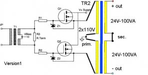
I attached 2 schems about my dilemmas....
I am also interested for the toroid version, but I am totaly confused too between the schematics and suggestions. (May be because my english is weak.) Could you post here a final and an unmistakable schematic/drawing of the toroid connections? and also could you tell me what kind of torroid would be the best for the output? I mean VA rating and/or primary and secondary voltages, or inductance or resistance?
Thanks!
Greets:
Tyimo
I attached 2 schems about my dilemmas....
Attachments
Hi Tyimo,
Thank you for your posts.
I am cooking supper at the moment but will put something together later this evening.
Best wishes,
Susan.
Thank you for your posts.
Tyimo said:Hi Susan!
I am also interested for the toroid version, but I am totaly confused too between the schematics and suggestions. (May be because my english is weak.) Could you post here a final and an unmistakable schematic/drawing of the toroid connections? and also could you tell me what kind of torroid would be the best for the output? I mean VA rating and/or primary and secondary voltages, or inductance or resistance?
Thanks!
Greets:
Tyimo
I attached 2 schems about my dilemmas....
I am cooking supper at the moment but will put something together later this evening.
Best wishes,
Susan.
I will try to answer Tyimo,
This one is correct:
http://www.diyaudio.com/forums/attachment.php?s=&postid=504258&stamp=1099420545
The image
-uwe
Tyimo said:Hi Susan!
I am also interested for the toroid version, but I am totaly confused too between the schematics and suggestions. (May be because my english is weak.) Could you post here a final and an unmistakable schematic/drawing of the toroid connections? and also could you tell me what kind of torroid would be the best for the output? I mean VA rating and/or primary and secondary voltages, or inductance or resistance?
Thanks!
Greets:
Tyimo
This one is correct:
http://www.diyaudio.com/forums/attachment.php?s=&postid=504258&stamp=1099420545
The image
-uwe
Tri-Filar Transformer Windings
Hi Everyone 🙂
Here is a pic of tri-filar winding. I hope this makes it a bit clearer.

http://www.susan-parker.co.uk/zeus-output-tx-trifilar-1.jpg
It is on an EI-120 bobbin and I am currently listening to it whilst typing - Jean Michel Jarre, The Concerts in China.
The windings are from standard three core electrical cable which I striped down, seperated out into three strands and then wound onto the bobbin.
There are aproximatly 60 turns for each wire.
This is the same mechanical details (size, laminations etc.) as the 75W transformer design on my website.
Sounds okay at low volume - bass not too thin.
Should work with any respectable sized mains transformer.
Quad-filar would be with four wires, and bi-filar with two.
Enamelled wire is preferable as one gets a much higher conductor cross section, but for trying out this seems a good start.
Best wishes,
Susan.
Hi Everyone 🙂
Here is a pic of tri-filar winding. I hope this makes it a bit clearer.
http://www.susan-parker.co.uk/zeus-output-tx-trifilar-1.jpg
It is on an EI-120 bobbin and I am currently listening to it whilst typing - Jean Michel Jarre, The Concerts in China.
The windings are from standard three core electrical cable which I striped down, seperated out into three strands and then wound onto the bobbin.
There are aproximatly 60 turns for each wire.
This is the same mechanical details (size, laminations etc.) as the 75W transformer design on my website.
Sounds okay at low volume - bass not too thin.
Should work with any respectable sized mains transformer.
Quad-filar would be with four wires, and bi-filar with two.
Enamelled wire is preferable as one gets a much higher conductor cross section, but for trying out this seems a good start.
Best wishes,
Susan.
Commentable thoughts
Hi Susan-Parker
Nice Transformer Detail Illustration
Very Nice!
Regards
ampman
Hi Susan-Parker
Nice Transformer Detail Illustration
Very Nice!
Regards
ampman
What about your cooking when you are online at the same timeSusan-Parker said:I am cooking supper at the moment but will put something together later this evening.
Best wishes,
Susan.
🙂I must also add that you Susan has created a very friendly, long and deep discussion aoout your "retro amp". Sometimes long threads about deep technical things tend to start tug of wars, pie throwing, food fights etc. which we moderators try to minimize as good as we can. As you can see diyaudio.com has a very mature level of conversation and those who can't follow the rules end up here
Gold star for good personality Susan.
 and Jocko will be proved wrong.
Please continue with the subject.

Hi all
Somebody may already have mentioned John Broskies article on simple push pull amplifiers in the Tubecad journal. The Tubecad journal is primarily about tubes, of course, but in the article below a few transformer coupled mosfet output stages are shown. One of the topologies is similar to the topology discussed in this thread.
Check this link:
http://www.tubecad.com/index_files/page0020.htm
Susan.
I am very impressed by your enthusiasm and the efforts you have done to share it with this forum. You have spent a lot of time helping forum members. Thanks.
Torben
mosfet constant current driver
Hello Susan,
do you think this ist a good variation of your design?
will it work well?
The Mosfet IRF 530N are all match to the same Bias Valtage at 10mV, some thing like ~ 4,22V.
And the three IRF 530N and the LM 317T are one the same heatsinks.
All the best - uwe.
Hello Susan,
do you think this ist a good variation of your design?
An externally hosted image should be here but it was not working when we last tested it.
will it work well?
The Mosfet IRF 530N are all match to the same Bias Valtage at 10mV, some thing like ~ 4,22V.
And the three IRF 530N and the LM 317T are one the same heatsinks.
All the best - uwe.
Hi Torben,
Thank you for your post and the reference.
Yes, these are variations of my design topology.
Please note however that for the design version shown using an inductor "Push-pull MOSFET class-A buffer/amplifier" the statement:
"This amplifier, unlike the previous MOSFET amplifiers, must be run in strict class-A, so the idle current will be quite high, at half of the peak current demand."
Is INCORRECT.
The bias level is set in the same way as for any of the others, i.e. in the mA range NOT amps.
(The problem with theory and not actually building stuff on the bench.)
===================
I am surprised he didn't let me know that he had written up about my efforts.
I am after all a user of B2SPICE, and have paid money for the product and the upgrades which even with the discount is still a good hundred pounds plus a pop.
===== Email Correspondence =====
> From: Susan JL Parker [mailto:susan@susan-parker.co.uk]
> Sent: Thursday, 23. January 2003 06:53
> To: 'John Broskie' johnb@beigebag.com
> Subject: Transformer amp circuit modeling in B2Spice
>
> Hi,
>
> I have been looking at your series of pages on RIAA and headphone amps
> with interest.
>
> I have the latest version of B2Spice V4 Pro, but I am having trouble
> (actually I have come to a grinding halt) understanding how to model
> transformers.
>
> My circuit is shown at: http://www.susan-parker.co.uk/zeus.htm
{ snip }
I can only suppose that as I am "only a girl" he didn't think it mattered 🙁
Which is a bit surprising as he also wrote:
> Susan,
> Thanks for the interest in my case studies. I am always
> thrilled to receive a technical email from a woman electronic
> practitioner (at my www.tubecad.com site, I garner one email a year
> from a female reader).
> I wish more women were interested, as our endeavor suffers from too
> much machismo.
Moving on to the technical side of things he wrote:
> Yes, modeling the transformer is difficult and the mutually
> coupled inductor in our program is ill-suited to the task. I have a
> friend who is going through 15 years of technical trade journals for
> articles on modeling transformers in SPICE.
And he seemed quite happy to promote his views on life:
> By the way, you might want to read my latest rant at the Tube
> CAD Journal, as it includes a letter to the editor of Electronic
> Products that I wrote, which touches on my preference for tube gear
> over solid-state.
Which I take to mean his preference for low or no overall negative feedback which glows in the dark over high negative feedback which just gets hot. A bit like the difference between a real coal or log fire and a central heating radiator. They both warm the room, but...
> Attached are several circuits that are minimalist in design and, in
> my view, jettison the need for transformers altogether. I particularly
> like the hybrid amplifier with feedback. (Compare the odd order
> harmonics with those from the amplifier with only two MOSFETs.)
I replied to this:
"Sorry - probably not going to like me anymore - but my amplifier is a TRANSFORMER amplifier. It is expressly designed around the use of TRANSFORMERS as the PRIMARY devices in the circuit. The MOSFETS are convenient way of doing the current thing, but are secondary components."
"I don’t want to "jettison" my transformers. Why do what everyone else has dome already, in a thousand different ways, when I can do something original and different? Which also works and IMO beats anything else at any price within its power capabilities - anything louder and I would prefer to be elsewhere anyway! Of course I might be a tiny bit biased, but then Audio does tend to get the passions going."
After a bit more discussion I finished off with:
"Anyway, the long and the short of it is that having spent years developing this beast I wanted to model it so I can get some "hard facts" behind my design work. Seems to me that spice does it all, except the transformers!
Ah well, back to the soldering iron.
Best wishes,
Susan."
==============
I have had a look at the relevant pages and don't see any acknowledgments anywhere. I can only wonder how many other people's stuff has had the same treatment?
BTW don't get me wrong, I think it is great that he is spending the time and effort to show all these circuits and describing them in some detail. Constructive efforts are to be commended.
But...
... there is that annoying little matter of COPYRIGHT!
Thank you.
More info to follow 🙂
Best wishes,
Susan.
Thank you for your post and the reference.
Herrmann said:Hi all
Somebody may already have mentioned John Broskies article on simple push pull amplifiers in the Tubecad journal. The Tubecad journal is primarily about tubes, of course, but in the article below a few transformer coupled mosfet output stages are shown. One of the topologies is similar to the topology discussed in this thread.
Check this link:
http://www.tubecad.com/index_files/page0020.htm
Yes, these are variations of my design topology.
Please note however that for the design version shown using an inductor "Push-pull MOSFET class-A buffer/amplifier" the statement:
"This amplifier, unlike the previous MOSFET amplifiers, must be run in strict class-A, so the idle current will be quite high, at half of the peak current demand."
Is INCORRECT.
The bias level is set in the same way as for any of the others, i.e. in the mA range NOT amps.
(The problem with theory and not actually building stuff on the bench.)
===================
I am surprised he didn't let me know that he had written up about my efforts.
I am after all a user of B2SPICE, and have paid money for the product and the upgrades which even with the discount is still a good hundred pounds plus a pop.
===== Email Correspondence =====
> From: Susan JL Parker [mailto:susan@susan-parker.co.uk]
> Sent: Thursday, 23. January 2003 06:53
> To: 'John Broskie' johnb@beigebag.com
> Subject: Transformer amp circuit modeling in B2Spice
>
> Hi,
>
> I have been looking at your series of pages on RIAA and headphone amps
> with interest.
>
> I have the latest version of B2Spice V4 Pro, but I am having trouble
> (actually I have come to a grinding halt) understanding how to model
> transformers.
>
> My circuit is shown at: http://www.susan-parker.co.uk/zeus.htm
{ snip }
I can only suppose that as I am "only a girl" he didn't think it mattered 🙁
Which is a bit surprising as he also wrote:
> Susan,
> Thanks for the interest in my case studies. I am always
> thrilled to receive a technical email from a woman electronic
> practitioner (at my www.tubecad.com site, I garner one email a year
> from a female reader).
> I wish more women were interested, as our endeavor suffers from too
> much machismo.
Moving on to the technical side of things he wrote:
> Yes, modeling the transformer is difficult and the mutually
> coupled inductor in our program is ill-suited to the task. I have a
> friend who is going through 15 years of technical trade journals for
> articles on modeling transformers in SPICE.
And he seemed quite happy to promote his views on life:
> By the way, you might want to read my latest rant at the Tube
> CAD Journal, as it includes a letter to the editor of Electronic
> Products that I wrote, which touches on my preference for tube gear
> over solid-state.
Which I take to mean his preference for low or no overall negative feedback which glows in the dark over high negative feedback which just gets hot. A bit like the difference between a real coal or log fire and a central heating radiator. They both warm the room, but...
> Attached are several circuits that are minimalist in design and, in
> my view, jettison the need for transformers altogether. I particularly
> like the hybrid amplifier with feedback. (Compare the odd order
> harmonics with those from the amplifier with only two MOSFETs.)
I replied to this:
"Sorry - probably not going to like me anymore - but my amplifier is a TRANSFORMER amplifier. It is expressly designed around the use of TRANSFORMERS as the PRIMARY devices in the circuit. The MOSFETS are convenient way of doing the current thing, but are secondary components."
"I don’t want to "jettison" my transformers. Why do what everyone else has dome already, in a thousand different ways, when I can do something original and different? Which also works and IMO beats anything else at any price within its power capabilities - anything louder and I would prefer to be elsewhere anyway! Of course I might be a tiny bit biased, but then Audio does tend to get the passions going."
After a bit more discussion I finished off with:
"Anyway, the long and the short of it is that having spent years developing this beast I wanted to model it so I can get some "hard facts" behind my design work. Seems to me that spice does it all, except the transformers!
Ah well, back to the soldering iron.
Best wishes,
Susan."
==============
I have had a look at the relevant pages and don't see any acknowledgments anywhere. I can only wonder how many other people's stuff has had the same treatment?
BTW don't get me wrong, I think it is great that he is spending the time and effort to show all these circuits and describing them in some detail. Constructive efforts are to be commended.
But...
... there is that annoying little matter of COPYRIGHT!
Susan.
I am very impressed by your enthusiasm and the efforts you have done to share it with this forum. You have spent a lot of time helping forum members. Thanks.
Torben
Thank you.
More info to follow 🙂
Best wishes,
Susan.
Upupa Epops said:To Herrman : Not similar, this is the same. 😉
Without acknowledgment to his source i.e. me!

We have rule here which says it's not allowed to publish private emails unless you have permission from the other person. I know you may be annoyed but this is not the issue here. Don't do this again please.
I can't find this particular rule in the text but we have it and if it's not written clearly maybe AudioFreak will.
Re: mosfet constant current driver
Hi dx.master,
Nice drawing.
Okay, a few points.
First: Input Transformer.
The XLR input. The GND should not be connected to ground as this can upset the balanced input.
You may find that you need to use the center tap as a return if you are driving the input transformer across both halves of the TI headphone amp TPA6120 as it doesn't like being bridged without it.
You can drive balanced from a push-pull line driver or pseudo-balanced from a CD/DVD/preamp headphone output.
If you use a 4 pin connector you then have the option of configuring the input as series or as parallel, and getting hold of the center tap as well.
Second: the bias circuit.
The IRF530N should have its Drain connected to it's Gate, not to the supply rail. The LM317T is then arranged to pull current through the IRF530N. You will need to add a Schottky diode in series to give you the bias offset.
Bias on the output mosfets needs to be higher than 10mV as measured on the two mosfets Drains as the mismatch between devices can be more than this. I would suggest a value between 100mV and 225mV depending on the output transformer (we are actually setting minimum current through the devices).
Third: Zeners
The zener protection should go the other side of the gate resistor - sorry, this is my fault for not updating my original 1994 drawing. I will be adding a schematic (as promised for last night - but I decided I wanted to draw it in DxDesigner (formally ViewDraw) as I wasn't happy with how the B2SPICE one was looking (difficulty in formating the information and adding annotations that I wanted) shortly with this shown correctly.
N.B. this version will work - just isn't recommended by International Rectifier "the purveyor of nice mosfets".
Forth: Output Transformer.
The loudspeaker load should be connected to the "24V - 30V" windings, not the 115 (unless perhaps you are driving electrostatic speaker membranes directly) as the primaries give you a step up which is not desirable (and are probably not wound well enough to give good coupling).
Note for the output transformer:
Using my normal configuration which is in effect a 2:1 step down the distortion levels into 8 ohms are well under (for the most part) 1%. Using a 4 ohm load increases the distortion levels somewhat - which is the same as using the speaker across the primaries.
Placing a 16 ohm load on the output dramatically decreases the distortion levels.
This is why I encourage the use of split secondaries to allow the transformer to be configured for 4:1 step down which reduces the distortion when driving a low 4 ohm load.
And why I prefer the use of a full transformer, not just a center tapped inductor. It is possible to load match and get better performance.
At the end of the day it is a matter of trade offs and I welcome the use of the toroid output transformer version as it hopefully helps people get started with trying out the amplifier without the significant up front costs of special transformers.
Once one has something working on the bench one can make measurements and perform listening tests. Experimentation with mosfet types, bias levels and transformer matching is easily done.
Then if one likes what one is hearing one can go to a "proper" built version on a regular chassis (aluminum, wood, glass, Perspex, cardboard, engineering plastics or ceramics, etc but not magnetic steel) to ensure that partners, pets, children, relatives, friends or oneself does not accidently get a shock 🙂
Hope this helps.
Best wishes,
Susan.
Hi dx.master,
Nice drawing.
dx.master said:Hello Susan,
do you think this ist a good variation of your design?
will it work well?
The Mosfet IRF 530N are all match to the same Bias Valtage at 10mV, some thing like ~ 4,22V.
And the three IRF 530N and the LM 317T are one the same heatsinks.
All the best - uwe.
Okay, a few points.
First: Input Transformer.
The XLR input. The GND should not be connected to ground as this can upset the balanced input.
You may find that you need to use the center tap as a return if you are driving the input transformer across both halves of the TI headphone amp TPA6120 as it doesn't like being bridged without it.
You can drive balanced from a push-pull line driver or pseudo-balanced from a CD/DVD/preamp headphone output.
If you use a 4 pin connector you then have the option of configuring the input as series or as parallel, and getting hold of the center tap as well.
Second: the bias circuit.
The IRF530N should have its Drain connected to it's Gate, not to the supply rail. The LM317T is then arranged to pull current through the IRF530N. You will need to add a Schottky diode in series to give you the bias offset.
Bias on the output mosfets needs to be higher than 10mV as measured on the two mosfets Drains as the mismatch between devices can be more than this. I would suggest a value between 100mV and 225mV depending on the output transformer (we are actually setting minimum current through the devices).
Third: Zeners
The zener protection should go the other side of the gate resistor - sorry, this is my fault for not updating my original 1994 drawing. I will be adding a schematic (as promised for last night - but I decided I wanted to draw it in DxDesigner (formally ViewDraw) as I wasn't happy with how the B2SPICE one was looking (difficulty in formating the information and adding annotations that I wanted) shortly with this shown correctly.
N.B. this version will work - just isn't recommended by International Rectifier "the purveyor of nice mosfets".
Forth: Output Transformer.
The loudspeaker load should be connected to the "24V - 30V" windings, not the 115 (unless perhaps you are driving electrostatic speaker membranes directly) as the primaries give you a step up which is not desirable (and are probably not wound well enough to give good coupling).
Note for the output transformer:
Using my normal configuration which is in effect a 2:1 step down the distortion levels into 8 ohms are well under (for the most part) 1%. Using a 4 ohm load increases the distortion levels somewhat - which is the same as using the speaker across the primaries.
Placing a 16 ohm load on the output dramatically decreases the distortion levels.
This is why I encourage the use of split secondaries to allow the transformer to be configured for 4:1 step down which reduces the distortion when driving a low 4 ohm load.
And why I prefer the use of a full transformer, not just a center tapped inductor. It is possible to load match and get better performance.
At the end of the day it is a matter of trade offs and I welcome the use of the toroid output transformer version as it hopefully helps people get started with trying out the amplifier without the significant up front costs of special transformers.
Once one has something working on the bench one can make measurements and perform listening tests. Experimentation with mosfet types, bias levels and transformer matching is easily done.
Then if one likes what one is hearing one can go to a "proper" built version on a regular chassis (aluminum, wood, glass, Perspex, cardboard, engineering plastics or ceramics, etc but not magnetic steel) to ensure that partners, pets, children, relatives, friends or oneself does not accidently get a shock 🙂
Hope this helps.
Best wishes,
Susan.
Sincere apology
So much for my cake and candle 🙁
I have only been on the DIY forum for a few weeks and this is my only thread.
I note that it has had at time of writing nearly twenty five thousand views and 375 posts. This places this topic in the top 12 of 5870 solid state topics.
I am thus doubly mortified at this unfortunate breach of DIYaudio etiquet on my part.
My apologies for this unwitting transgression.
The guy is a company who makes money out of this stuff including me and it was a matter of quoting a SMALL part of an email to prove precedence - otherwise my anxiety is that those good people viewing this topic might think that I have been underhand.
However I accept that I was wrong to do so and will not do so again so I unreservedly apologise for this unwitting mistake...
... and unwritten transgression.
After all ignorance of the law is no excuse.
Susan.
So much for my cake and candle 🙁
I have only been on the DIY forum for a few weeks and this is my only thread.
I note that it has had at time of writing nearly twenty five thousand views and 375 posts. This places this topic in the top 12 of 5870 solid state topics.
I am thus doubly mortified at this unfortunate breach of DIYaudio etiquet on my part.
peranders said:
We have rule here which says it's not allowed to publish private emails unless you have permission from the other person. I know you may be annoyed but this is not the issue here. Don't do this again please.
My apologies for this unwitting transgression.
The guy is a company who makes money out of this stuff including me and it was a matter of quoting a SMALL part of an email to prove precedence - otherwise my anxiety is that those good people viewing this topic might think that I have been underhand.
However I accept that I was wrong to do so and will not do so again so I unreservedly apologise for this unwitting mistake...
I can't find this particular rule in the text but we have it and if it's not written clearly maybe AudioFreak will.
... and unwritten transgression.
After all ignorance of the law is no excuse.
Susan.
 You are forgiven for this one time offence and I'm sure you have created a statement, the "Zeus amp" and we all know where it comes from. It's not every day someone presents an odd amplifier topology and creates this huge interest/curiosity. Your amp may be something for those who believe that "less is more". Notice all Gainclone builders, a LM3875 contains surely at least 100 parts! How many parts does this amp contain?
Why not start to develop a reproducable design?
 A group buy maybe with special winded transformers.
Re: Re: mosfet constant current driver
Dear Susan,
fantatstic Comments,
i redraw the picture and think it's now correct even better.
Yes i use ExpressPCB .
done.
I hope you write wat i have done.
Yes i saw at IRF.COM, done.
It's not so clear for me, but I will try it the next days..
my bad english...
greeting - uwe
Dear Susan,
fantatstic Comments,
i redraw the picture and think it's now correct even better.
An externally hosted image should be here but it was not working when we last tested it.
Susan-Parker said:Hi dx.master,
Nice drawing.
Yes i use ExpressPCB .
First: Input Transformer.
The XLR input. The GND should not be connected to ground as this can upset the balanced input.
You may find that you need to use the center tap as a return if you are driving the input transformer across both halves of the TI headphone amp TPA6120 as it doesn't like being bridged without it.
You can drive balanced from a push-pull line driver or pseudo-balanced from a CD/DVD/preamp headphone output.
If you use a 4 pin connector you then have the option of configuring the input as series or as parallel, and getting hold of the center tap as well.
done.
Second: the bias circuit.
The IRF530N should have its Drain connected to it's Gate, not to the supply rail. The LM317T is then arranged to pull current through the IRF530N. You will need to add a Schottky diode in series to give you the bias offset.
Bias on the output mosfets needs to be higher than 10mV as measured on the two mosfets Drains as the mismatch between devices can be more than this. I would suggest a value between 100mV and 225mV depending on the output transformer (we are actually setting minimum current through the devices).
I hope you write wat i have done.
Third: Zeners
The zener protection should go the other side of the gate resistor - sorry, this is my fault for not updating my original 1994 drawing. I will be adding a schematic (as promised for last night - but I decided I wanted to draw it in DxDesigner (formally ViewDraw) as I wasn't happy with how the B2SPICE one was looking (difficulty in formating the information and adding annotations that I wanted) shortly with this shown correctly.
N.B. this version will work - just isn't recommended by International Rectifier "the purveyor of nice mosfets".
Yes i saw at IRF.COM, done.
Forth: Output Transformer.
The loudspeaker load should be connected to the "24V - 30V" windings, not the 115 (unless perhaps you are driving electrostatic speaker membranes directly) as the primaries give you a step up which is not desirable (and are probably not wound well enough to give good coupling).
Note for the output transformer:
Using my normal configuration which is in effect a 2:1 step down the distortion levels into 8 ohms are well under (for the most part) 1%. Using a 4 ohm load increases the distortion levels somewhat - which is the same as using the speaker across the primaries.
Placing a 16 ohm load on the output dramatically decreases the distortion levels.
This is why I encourage the use of split secondaries to allow the transformer to be configured for 4:1 step down which reduces the distortion when driving a low 4 ohm load.
And why I prefer the use of a full transformer, not just a center tapped inductor. It is possible to load match and get better performance.
It's not so clear for me, but I will try it the next days..
my bad english...
greeting - uwe
Re: Re: Re: mosfet constant current driver
Hi dx.master,
That was quick.
Thank you 🙂
Don't worry, a picture is worth a 1000 words.
Interesting version of the bias circuit.
I like the slow start and doide discharge.
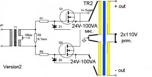
Output for a torroid should however be like this with only the low voltage windings being used:

Otherwise excellent 🙂
Look forward to hearing your progress.
Many thanks.
Best wishes,
Susan.
Hi dx.master,
That was quick.
dx.master said:Dear Susan,
fantatstic Comments,
i redraw the picture and think it's now correct even better.
An externally hosted image should be here but it was not working when we last tested it.
It's not so clear for me, but I will try it the next days..
my bad english...
greeting - uwe
Thank you 🙂
Don't worry, a picture is worth a 1000 words.
Interesting version of the bias circuit.
I like the slow start and doide discharge.
Output for a torroid should however be like this with only the low voltage windings being used:
Otherwise excellent 🙂
Look forward to hearing your progress.
Many thanks.
Best wishes,
Susan.
- Home
- Amplifiers
- Solid State
- Zero Feedback Impedance Amplifiers