Re: Lateral FETs
Hi wrenchone,
Thanks again for your insightful post 🙂
===
Hi Patrick,
Okay, I will get in touch at the end of the weekend - rush rush at the moment - and discuss 🙂
Best wishes,
Susan.
Hi wrenchone,
Thanks again for your insightful post 🙂
===
Hi Patrick,
EUVL said:Susan,
> Many thanks for the "nudge"
The offer for 2SK's is still on. Why not give it a try ? : )
You don't get them from Digikey.
I guess I have some private interest (NOT financial) to see how lateral FETs compares in your application. : )
Patrick
Okay, I will get in touch at the end of the weekend - rush rush at the moment - and discuss 🙂
Best wishes,
Susan.
Get him to join diyaudio and contribute to this thread!tubesguy said:Seriously, I'll drop off a copy of your circuit. May bring a smile to his face, who know? - Pat

Commentable thoughts
Hi CIRCLOTRON ur absolutely rite in this case but u have left some important phenomena occuring during full power drive conditions.
When Vertical Mosfets amps are driven at their full power they output high current which then forces the the Famous RDS to ACT according to the POSITIVE Temp. COEFF Which inturns causes the output current to be sum of Shared Branches of Current through Individual Mosfet in a group therefore this phenomena forces the current sharing duing high drive conditions and thus prevent thermal runaway of mosfets , as they simply self regulate the RDS according to temp. rise.
Simply biasing a group of parallel Mosfets with source or drain resistors wont help in current sharing at idle conditions . One has to match the VGS of Mosfets at tight tolerances to eliminate non current sharing.
We have done lot of Practical Realworld experimentation in 45Degree Celcius ambient temp, in which source or drain resistors have not played any significant role in current sharing.
Secondly a biasing netwok is must for any Class-AB or Class-A amp with Proper thermal tracking.
With Regards
Workhorse Technologies
Circlotron said:
On resistance = PTC.
Threshold voltage = NTC ~5.5mV per deg C.
Minimum Rdson is irrelevant if you are using the device in linear mode. Vth is everything.
Hi CIRCLOTRON ur absolutely rite in this case but u have left some important phenomena occuring during full power drive conditions.
When Vertical Mosfets amps are driven at their full power they output high current which then forces the the Famous RDS to ACT according to the POSITIVE Temp. COEFF Which inturns causes the output current to be sum of Shared Branches of Current through Individual Mosfet in a group therefore this phenomena forces the current sharing duing high drive conditions and thus prevent thermal runaway of mosfets , as they simply self regulate the RDS according to temp. rise.
Simply biasing a group of parallel Mosfets with source or drain resistors wont help in current sharing at idle conditions . One has to match the VGS of Mosfets at tight tolerances to eliminate non current sharing.
We have done lot of Practical Realworld experimentation in 45Degree Celcius ambient temp, in which source or drain resistors have not played any significant role in current sharing.
Secondly a biasing netwok is must for any Class-AB or Class-A amp with Proper thermal tracking.
With Regards
Workhorse Technologies
New output Transi ?
Hello Susan,
ist this change auf Tr2 possible ?
This is a the picture of the new Tr2 and Tr3:
Please look also at this picture:
Im my Stock ar only these Transi for the output stage.
All the best from Germany
Hello Susan,
ist this change auf Tr2 possible ?
This is a the picture of the new Tr2 and Tr3:
An externally hosted image should be here but it was not working when we last tested it.
Please look also at this picture:
An externally hosted image should be here but it was not working when we last tested it.
Im my Stock ar only these Transi for the output stage.
All the best from Germany
I just got finished selecting IRF540s for the output stage of my push-pull prototype. I used ST devices obtained through Digi-Key. To select FETs, I used a current-limited power supply set to 200ma short circuit current and 10V open circuit. I also used a jig that hooked gate and drain together and grounded the source. A couple of DVMs were used to monitor voltage and current. I ended up selecting two pairs that were exactly 3.91V out of about 20 devices - not a bad haul, especially since there were several other matched pairs at other Vgs values.
My big surprise came when I tried to select bias FETs. Simulation results showed that an IRF 530 would work to bias the 540 output devices if the 530 was bised at 30ma. However, I tried some 533s in my jig, ad they dropped only about 1.6Vat the desired bias current. I then tried some Siliconix IRF612s, which were much closer to the money at 3.6V at 30V bias current. I will use the 612s in the bias circuit and either up the bias current a little or accept a somewhat lower quiescent current in my output FETs. This wasd not a problem with FET diamond buffers I built, as I used the ratio of two resistors as well as the relative FET Vgs to set output bias current.
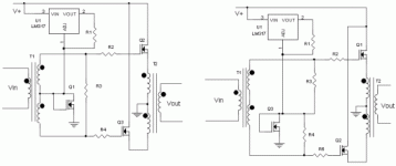
Attached are two possible bias circuits for the push-pull amp. I'll probably end up using the one on the left. Protection zeners and bypass caps were left out for clarity - these will be needed in a real-world implementation.
My big surprise came when I tried to select bias FETs. Simulation results showed that an IRF 530 would work to bias the 540 output devices if the 530 was bised at 30ma. However, I tried some 533s in my jig, ad they dropped only about 1.6Vat the desired bias current. I then tried some Siliconix IRF612s, which were much closer to the money at 3.6V at 30V bias current. I will use the 612s in the bias circuit and either up the bias current a little or accept a somewhat lower quiescent current in my output FETs. This wasd not a problem with FET diamond buffers I built, as I used the ratio of two resistors as well as the relative FET Vgs to set output bias current.
Attached are two possible bias circuits for the push-pull amp. I'll probably end up using the one on the left. Protection zeners and bypass caps were left out for clarity - these will be needed in a real-world implementation.
Attachments
Question to Susan:
Hi Susan,
Do you have any experience with mutual coupling of the input and the output transformer? Especially when using EI cores?
Reason I ask is that I just spend a day chasing a persistent hum in a couple of Hiraga single-FET power amps (basically one-half of your amp, sans the input xformer). Turned out that the guy who built those amps didn't follow one critical recommendation from Hiraga: He put in the power transformer and the output transformer with the same orientation, and that was enough to induce around 3mV hum at the (loaded) speaker terminals. Even with the xformers physically separated about 40 cm (15.748 inch)!
Rotating the power xformer 90 degrees lowered the hum to 300uV, no longer audible more than a feet away from the speaker.
This may also be an issue with your design.
Jan Didden
I just wound around 18 turns of 2.5 mm² speaker wire around a 19,11 cm² EI core, so that's 36 turns in total.
This sounds alot better than a old power transformer, probably because it is bifilar wound, the bass is a bit less so I guess I need some thinner wire to get more turns.
The bass goes away completely when I take off the I bit of the core.
This sounds alot better than a old power transformer, probably because it is bifilar wound, the bass is a bit less so I guess I need some thinner wire to get more turns.
The bass goes away completely when I take off the I bit of the core.
Re: New output Transi ?
Hi hostmaster,
Thank you for your post and trying my amplifier design.
I had a look but couldn't find a matched pair of transformers to try this out.
This configuration is interesting and should give some results however the high frequency response will be limited as the windings lose coupling. This may be high enough to not matter.
To maintain the coupling you may have to place the speaker across the primaries.
(You could also try using one as the input transformer if you don't have anything smaller.)
Worth while having a go - will be interested to hear how you do.
Best wishes,
Susan.
The Zeta amps look interesting 🙂
Hi hostmaster,
Thank you for your post and trying my amplifier design.
hostmaster said:Hello Susan,
ist this change auf Tr2 possible ?
Please look also at this picture:
An externally hosted image should be here but it was not working when we last tested it.
Im my Stock ar only these Transi for the output stage.
All the best from Germany
I had a look but couldn't find a matched pair of transformers to try this out.
This configuration is interesting and should give some results however the high frequency response will be limited as the windings lose coupling. This may be high enough to not matter.
To maintain the coupling you may have to place the speaker across the primaries.
(You could also try using one as the input transformer if you don't have anything smaller.)
Worth while having a go - will be interested to hear how you do.
Best wishes,
Susan.
The Zeta amps look interesting 🙂
Hi wrenchone,
Thank you for your post.
I am using a schottky diode in series with the mosfet to give me the required voltage difference to get the desired bias level.
I would use the left one with the center tapped transformer if at all possible as with matched windings the distortion is a little lower in the measurments I have made so far.
Best wishes,
Susan.
Thank you for your post.
wrenchone said:My big surprise came when I tried to select bias FETs. Simulation results showed that an IRF 530 would work to bias the 540 output devices if the 530 was bised at 30ma. However, I tried some 533s in my jig, ad they dropped only about 1.6Vat the desired bias current. I then tried some Siliconix IRF612s, which were much closer to the money at 3.6V at 30V bias current. I will use the 612s in the bias circuit and either up the bias current a little or accept a somewhat lower quiescent current in my output FETs. This wasd not a problem with FET diamond buffers I built, as I used the ratio of two resistors as well as the relative FET Vgs to set output bias current.
I am using a schottky diode in series with the mosfet to give me the required voltage difference to get the desired bias level.
Attached are two possible bias circuits for the push-pull amp. I'll probably end up using the one on the left. Protection zeners and bypass caps were left out for clarity - these will be needed in a real-world implementation. [/B]
I would use the left one with the center tapped transformer if at all possible as with matched windings the distortion is a little lower in the measurments I have made so far.
Best wishes,
Susan.
Hi Jan,
Thanks for your question.
Somewhat to my surprise there seems to be little problem using the two side by side. See pic of the amp, you can see the input transformer snuggled next to the output transformer. I tried to keep a bit of distance to the power supply transformer.
I did get a couple of Mumetal cases when I originally got the input transformers from Sowter, but they don't appear to be needed.
One problem with single ended amplifiers.
My amplifier has a low input impedance of 600 ohms or less whereas the Hiraga will probably be quite high?
I assume the Hiraga is using the FET as a gain stage?
It is always recommended to place the two transformers at 90 degrees to each other. I would use a toroid for power if possible which goes a long way to solving this - however it is more difficult to make a toroid look pretty 🙂
Good improvement.
I have not found this to be a problem as one of the great strengths of the push-pull design is the cancellation of external signals.
Also my amp doesn't have any audible hum or hiss. I cannot hear anything from a speaker when the amplifier is on without an input. That is with my ear right up to the cones. And I can touch the input of the amplifier with a finger at the same time and not have my hearing blasted.
Best wishes,
Susan.
Thanks for your question.
janneman said:Hi Susan,
Do you have any experience with mutual coupling of the input and the output transformer? Especially when using EI cores?
Somewhat to my surprise there seems to be little problem using the two side by side. See pic of the amp, you can see the input transformer snuggled next to the output transformer. I tried to keep a bit of distance to the power supply transformer.
I did get a couple of Mumetal cases when I originally got the input transformers from Sowter, but they don't appear to be needed.
Reason I ask is that I just spend a day chasing a persistent hum in a couple of Hiraga single-FET power amps (basically one-half of your amp, sans the input xformer). Turned out that the guy who built those amps didn't follow one critical recommendation from Hiraga: He put in the power transformer and the output transformer with the same orientation, and that was enough to induce around 3mV hum at the (loaded) speaker terminals. Even with the xformers physically separated about 40 cm (15.748 inch)!
One problem with single ended amplifiers.
My amplifier has a low input impedance of 600 ohms or less whereas the Hiraga will probably be quite high?
I assume the Hiraga is using the FET as a gain stage?
It is always recommended to place the two transformers at 90 degrees to each other. I would use a toroid for power if possible which goes a long way to solving this - however it is more difficult to make a toroid look pretty 🙂
Rotating the power xformer 90 degrees lowered the hum to 300uV, no longer audible more than a feet away from the speaker.
This may also be an issue with your design.
Jan Didden
Good improvement.
I have not found this to be a problem as one of the great strengths of the push-pull design is the cancellation of external signals.
Also my amp doesn't have any audible hum or hiss. I cannot hear anything from a speaker when the amplifier is on without an input. That is with my ear right up to the cones. And I can touch the input of the amplifier with a finger at the same time and not have my hearing blasted.
Best wishes,
Susan.
Hi bobo1on1
Thank you for the update 🙂
A few more turns should improve the bass. 1.0 mm² or a little less should be fine and I would guess that ordinary hookup wire could be used for this even though the insulation is a bit thicker than using enameled wire.
The loss of bass corresponds to the large reduction in inductance with the opening of the magnetic circuit.
Good information, thanks.
Best wishes,
Susan.
Thank you for the update 🙂
bobo1on1 said:I just wound around 18 turns of 2.5 mm² speaker wire around a 19,11 cm² EI core, so that's 36 turns in total.
This sounds alot better than a old power transformer, probably because it is bifilar wound, the bass is a bit less so I guess I need some thinner wire to get more turns.
The bass goes away completely when I take off the I bit of the core.
A few more turns should improve the bass. 1.0 mm² or a little less should be fine and I would guess that ordinary hookup wire could be used for this even though the insulation is a bit thicker than using enameled wire.
The loss of bass corresponds to the large reduction in inductance with the opening of the magnetic circuit.
Good information, thanks.
Best wishes,
Susan.
Hi All,
When you use two transformers that are parallel connected it is not push-pull. With toroids the cores are going to be magnetically biased, whereas with E-I at least you can gap the I.
Cheers ........... Graham.
When you use two transformers that are parallel connected it is not push-pull. With toroids the cores are going to be magnetically biased, whereas with E-I at least you can gap the I.
Cheers ........... Graham.
Re: Re: New output Transi ?
Hi Susan,
thank you for your answer,
i don't understand this
Is this the schema "across the primaries"?
I have buy one 2 x 12 V 30 VA, i hope it will "run" as soon a have it at home.
I will try it out and then i tell you about the mods ..
- uwe
Hi Susan,
thank you for your answer,
i don't understand this
Susan-Parker said:This configuration is interesting and should give some results however the high frequency response will be limited as the windings lose coupling. This may be high enough to not matter.
To maintain the coupling you may have to place the speaker across the primaries.
Is this the schema "across the primaries"?
An externally hosted image should be here but it was not working when we last tested it.
(You could also try using one as the input transformer if you don't have anything smaller.)
I have buy one 2 x 12 V 30 VA, i hope it will "run" as soon a have it at home.
Worth while having a go - will be interested to hear how you do.
I will try it out and then i tell you about the mods ..
- uwe
Connecting the speaker to the primaries means you will have to connect the speaker to the sources of the fets, because when you use a mains transformer you are using the secondaries as primaries.
Hi Graham,
Thank you for your post. I hope you are keeping well.
Graham is quite correct in that the transformers will be magnetically biased.
My experience has been that for the large cores and small bias levels that are being used this is not a problem (we are using mA, not amps as would be the case with a single ended design).
However this is with EI cores although they were just straight EI "top n' tail" interleaved without any deliberate gap.
The configuration with the two separate transformers should give some results - but is far from ideal. However if they are to hand and can be tried out then I don't see any problem in having a go.
Just remember to have a fuse in the supply rail after the storage capacitor in case a transformer does saturate.
And as the toroids have a closer coupling it may be that this configuration with two separate transformers will not work well at all - but if the bits are available? This is half the fun of DIY audio after all 🙂
And one can also use a lower DC bias level of say 25 to 30 mA - which will still work but for a (slightly) higher distortion level.
With 100 VA transformers you should be looking at 25 watts maximum (e.g. 14 volts ac rms into 8 ohms) for a full bandwidth audio. As this is across the primaries that gives a power supply of around 20 volts DC max (allowing for a bit of headroom), and this could be less.
It is not advisable to run off a significantly higher supply rail than that which is sufficient to drive the desired/calculated maximum power into the speaker/load as with the transformer coupled input there is no intrinsic limit to the gate drive (unless one puts a pair of zeners back to back across Rterm) and the output will quite happily try to follow.
Driving the amplifier output hard into the power rail on the other hand isn't a problem as the mosfets simply run out of get-go. Because the negative rail is generated by the transformer and not from a DC power supply there is no possibility of the output stage shredding itself in overdrive conditions unlike conventional solid state power amplifiers.
As previously mentioned with low gate voltage drive mosfets you could run off a car battery - just don't forget the fuse.
Thank you Graham for the comment and a reminder on the bias levels.
Best wishes,
Susan.
P.S. Note to All:
FUSE - Please remember to ALWAYS use a fuse in the supply rail to the mosfets AFTER the storage/smoothing capacitor(s).
Thank you for your post. I hope you are keeping well.
Graham Maynard said:Hi All,
When you use two transformers that are parallel connected it is not push-pull. With toroids the cores are going to be magnetically biased, whereas with E-I at least you can gap the I.
Cheers ........... Graham.
Graham is quite correct in that the transformers will be magnetically biased.
My experience has been that for the large cores and small bias levels that are being used this is not a problem (we are using mA, not amps as would be the case with a single ended design).
However this is with EI cores although they were just straight EI "top n' tail" interleaved without any deliberate gap.
The configuration with the two separate transformers should give some results - but is far from ideal. However if they are to hand and can be tried out then I don't see any problem in having a go.
Just remember to have a fuse in the supply rail after the storage capacitor in case a transformer does saturate.
And as the toroids have a closer coupling it may be that this configuration with two separate transformers will not work well at all - but if the bits are available? This is half the fun of DIY audio after all 🙂
And one can also use a lower DC bias level of say 25 to 30 mA - which will still work but for a (slightly) higher distortion level.
With 100 VA transformers you should be looking at 25 watts maximum (e.g. 14 volts ac rms into 8 ohms) for a full bandwidth audio. As this is across the primaries that gives a power supply of around 20 volts DC max (allowing for a bit of headroom), and this could be less.
It is not advisable to run off a significantly higher supply rail than that which is sufficient to drive the desired/calculated maximum power into the speaker/load as with the transformer coupled input there is no intrinsic limit to the gate drive (unless one puts a pair of zeners back to back across Rterm) and the output will quite happily try to follow.
Driving the amplifier output hard into the power rail on the other hand isn't a problem as the mosfets simply run out of get-go. Because the negative rail is generated by the transformer and not from a DC power supply there is no possibility of the output stage shredding itself in overdrive conditions unlike conventional solid state power amplifiers.
As previously mentioned with low gate voltage drive mosfets you could run off a car battery - just don't forget the fuse.
Thank you Graham for the comment and a reminder on the bias levels.
Best wishes,
Susan.
P.S. Note to All:
FUSE - Please remember to ALWAYS use a fuse in the supply rail to the mosfets AFTER the storage/smoothing capacitor(s).
Hi bobo1on1,
Thank you for the clarification.
My apologies to hostmaster for the confusion and not being careful enough in describing the transformers' connections which is tricky given that we are running the transformers backwards.
Best wishes,
Susan.
bobo1on1 said:Connecting the speaker to the primaries means you will have to connect the speaker to the sources of the fets, because when you use a mains transformer you are using the secondaries as primaries.
Thank you for the clarification.
My apologies to hostmaster for the confusion and not being careful enough in describing the transformers' connections which is tricky given that we are running the transformers backwards.
Best wishes,
Susan.
TRANSFORMERWINDINGS
Hi Susan! Thank you very much for sharing your idees and knowledge with us.
I have two 800 VA E-I transformers that im thinking of rewinding. How would i do that. I have never worked with transformers before and i dont know what all of your strange words mean.
What is bifilar,trifilar and so forth???
I have been reading all previous pages trying to catch bits and pieces but its hard to understand what and how to do it.
Re: TRANSFORMERWINDINGS
"Regular" winding is one wire, wound round and round.
Bi-Filar is TWO wires taken together (side by side) and wound
round and round together.
Tri-Filar is THREE wires taken together and wound round and round.
150 turns of Bifilar wire is ONE layer and has 2x the total length of wire as does 150 turns of regular winding, the fatness of the windings is also 2x that of a single wire wound 150 times, but about the same as TWO layers of single wound wire @ 150 turns.
_-_-bear
Circlomanen said:Hi Susan! Thank you very much for sharing your idees and knowledge with us.
I have two 800 VA E-I transformers that im thinking of rewinding. How would i do that. I have never worked with transformers before and i dont know what all of your strange words mean.
What is bifilar,trifilar and so forth???
I have been reading all previous pages trying to catch bits and pieces but its hard to understand what and how to do it.
"Regular" winding is one wire, wound round and round.
Bi-Filar is TWO wires taken together (side by side) and wound
round and round together.
Tri-Filar is THREE wires taken together and wound round and round.
150 turns of Bifilar wire is ONE layer and has 2x the total length of wire as does 150 turns of regular winding, the fatness of the windings is also 2x that of a single wire wound 150 times, but about the same as TWO layers of single wound wire @ 150 turns.
_-_-bear
Re: Re: TRANSFORMERWINDINGS
Hi Circlomanen,
A good question as this is something that took me quite a while to sort out (and I would readily admit some of the squiggly flux maths is still impenetrable) so despite my best efforts it is all to easy for me to glibly use these terms without being totally clear to everyone else.
I think that the best thing is for me to write up a page on transformer construction that I can put up on my website rather than try to describe it in a post which will get lost in short order.
If I can ask you to bear with me for a short time as this will take a day or to organize.
===
Hi Bear,
Thank you for the clarification...
... much appreciated.
Best wishes,
Susan.
Hi Circlomanen,
Circlomanen said:Hi Susan! Thank you very much for sharing your idees and knowledge with us.
I have two 800 VA E-I transformers that im thinking of rewinding. How would i do that. I have never worked with transformers before and i dont know what all of your strange words mean.
What is bifilar,trifilar and so forth???
I have been reading all previous pages trying to catch bits and pieces but its hard to understand what and how to do it.
A good question as this is something that took me quite a while to sort out (and I would readily admit some of the squiggly flux maths is still impenetrable) so despite my best efforts it is all to easy for me to glibly use these terms without being totally clear to everyone else.
I think that the best thing is for me to write up a page on transformer construction that I can put up on my website rather than try to describe it in a post which will get lost in short order.
If I can ask you to bear with me for a short time as this will take a day or to organize.
===
Hi Bear,
Thank you for the clarification...
bear said:
"Regular" winding is one wire, wound round and round.
Bi-Filar is TWO wires taken together (side by side) and wound
round and round together.
Tri-Filar is THREE wires taken together and wound round and round.
150 turns of Bifilar wire is ONE layer and has 2x the total length of wire as does 150 turns of regular winding, the fatness of the windings is also 2x that of a single wire wound 150 times, but about the same as TWO layers of single wound wire @ 150 turns.
_-_-bear
... much appreciated.
Best wishes,
Susan.
Question : Input-Tranfomfer
Hello,
I am reading this thread since 3 days and I must say - Susan - congratulations. Very refreshing.
Since I am no "transformer-guy" I would like put some questions :
1.) Would it be possible to create a input-transformer which would be able to drive TWO of these amps in one ? Why ? - Because I thought of trying this amp with an bi-amping-configuration. So it is possible to tweak around with a 1+x+x- Transformer (maybe by Sowter) to be able to drive TWO amps at once ( 4 MosFets) - hence two chanel ?
Or would I need TWO transformers to create such a setup ?
I touhgt of a typical kind of "distribution-transformer" like often used in professional setups.
2.) Will Sowter be able to custom-create such a output-transformer at an affordable price. I still have no ides how to get the stuff for such a transfomrer or even to manage to build on myself ?
3.) You describe on your web-site a test-setup with toroid transformers. Fine - but I do not understand how you use the STEREO-output of the CD-Porti to drive the input trans ? The CD-Porti-Out is not actual a real BALANCED-OUT ? You use only left and right to create balanced or how does it work ? I am confused, since the porti left + right out is not quite a real differential out ???
I would use a differential-out from a high-end soundcard to be able to drive the 600 Ohm load ... But how to connect properly ? Will the two secondaries be connected in serial ? Where is the ground. I understand differentail as +/- and gound ????
3b.) For the toroid-setup you use only the secondaries of the transformer ???? 😕 How do you connect the secondaries to get the proper inout / output relation ???? I have to admit that I do not know how this is managed ????
Since I am very keen o trying this setup for myself, it would help me a lot if you would be so nice to give me a hint.
Thank you in advance.
drummer44
- Home
- Amplifiers
- Solid State
- Zero Feedback Impedance Amplifiers