Zeus Line Level THD
Hi Jorge,
Yes, of course.
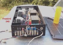
See my Zeus MOSFET SE Preamp & PP Power Amp System Test, i.e. full line level end to end, not just the pre or the power amp, and which is a bird's nest everything hanging out on the bench test too.
Zeus SE MOSFET Preamp PP MOSFET Power Amp Tests
1.1 watts = 2.89 volts into 8 ohms - 0.0054% THD
2.1 watts = 4.09 volts into 8 ohms - 0.0079% THD
4.2 watts = 5.78 volts into 8 ohms - 0.0110% THD
Note that the even 2nd harmonic is c. 4dB higher than the odd third harmonic in these measurements.
Huge, is it not?
Best wishes,
Susan.
Hi Jorge,
Zero feedback amp sound so lively but come with huge thd.
Yes, of course.
See my Zeus MOSFET SE Preamp & PP Power Amp System Test, i.e. full line level end to end, not just the pre or the power amp, and which is a bird's nest everything hanging out on the bench test too.
Zeus SE MOSFET Preamp PP MOSFET Power Amp Tests
1.1 watts = 2.89 volts into 8 ohms - 0.0054% THD
2.1 watts = 4.09 volts into 8 ohms - 0.0079% THD
4.2 watts = 5.78 volts into 8 ohms - 0.0110% THD
Note that the even 2nd harmonic is c. 4dB higher than the odd third harmonic in these measurements.
Huge, is it not?
Best wishes,
Susan.
Last edited:
Decades ago, I have used power transformer cores for audio, not super hi-fi, in PA amps, car stereo power amps, and other general purpose audio power amps, with fairly good results. I'd be interested in some discussion regarding performance limitations expected by use of power transformer iron in audio use. Thanks.
Well, I guess frequency response is the main limitation and toroidal cores will perform best in this regard.
I also suspect that low level details will be lost and I cannot suggest anything to remedy this.
Toroid Transformers
Hi Mike,
For my multi-filar output transformers the use of a toroid will benefit LF extension. However the HF extension is not so good with drop off beyond 20 kHz when run into a constant impedance load (e.g. 8 ohms).
Menno Van der Veen (who is a really nice guy) has devised special winding techniques to overcome this with the tube/valve output transformers (available from Plitron) but note that these have a considerable impedance ratio between input and output.
In my own tests I wound both quad-filar and interlayered P:S😛 bi-filar windings on a pair of test transformers (using 500VA cores) and they both gave the same sort of HF drop-off. I believe that this is to do with the non uniform winding one gets going round on a circular path. As with everything, more testing can be done here, time permitting.
If the speaker load has a rising impedance, then this issue may well not be a problem. Particularly if one custom designs the speaker and crossovers to compensate.
Personally I am moving towards bi-amping my main speakers with separate output amps (PP for the LF and a SE driver for the HF) with the crossover done at the 600 ohms line driver stage.
As to loss of detail...
Are you referring to Menno's 2011 AES paper "Signal Level and Frequency Dependant Losses Inside Audio Signal Transformers and How to Prevent Those" (which you can find here: Menno van der Veen's audio website )?
... listening tests of my system don't seem to show this as a problem. One has to use good grade of core of course, minimum M6 silicon steel laminations.
People (not just myself) can hear detail off vinyl (analogue mastered using magnetic tape) that simply isn't there on CD. So I don't think this is the limiting factor.
Best wishes,
Susan.
Hi Mike,
Well, I guess frequency response is the main limitation and toroidal cores will perform best in this regard.
I also suspect that low level details will be lost and I cannot suggest anything to remedy this.
For my multi-filar output transformers the use of a toroid will benefit LF extension. However the HF extension is not so good with drop off beyond 20 kHz when run into a constant impedance load (e.g. 8 ohms).
Menno Van der Veen (who is a really nice guy) has devised special winding techniques to overcome this with the tube/valve output transformers (available from Plitron) but note that these have a considerable impedance ratio between input and output.
In my own tests I wound both quad-filar and interlayered P:S😛 bi-filar windings on a pair of test transformers (using 500VA cores) and they both gave the same sort of HF drop-off. I believe that this is to do with the non uniform winding one gets going round on a circular path. As with everything, more testing can be done here, time permitting.
If the speaker load has a rising impedance, then this issue may well not be a problem. Particularly if one custom designs the speaker and crossovers to compensate.
Personally I am moving towards bi-amping my main speakers with separate output amps (PP for the LF and a SE driver for the HF) with the crossover done at the 600 ohms line driver stage.
As to loss of detail...
Are you referring to Menno's 2011 AES paper "Signal Level and Frequency Dependant Losses Inside Audio Signal Transformers and How to Prevent Those" (which you can find here: Menno van der Veen's audio website )?
... listening tests of my system don't seem to show this as a problem. One has to use good grade of core of course, minimum M6 silicon steel laminations.
People (not just myself) can hear detail off vinyl (analogue mastered using magnetic tape) that simply isn't there on CD. So I don't think this is the limiting factor.
Best wishes,
Susan.
Hi Susan,
I was commenting on using using regular power transformer cores for audio signals ( as per imfree707's question ) and was assuming that they aren't really very good grade.
Based on my experiences with sabre buffalo DAC it won't be long before it's possible for digital to challenge analogue system low level detail. As long as implemented well, they can be both finely detailed and very pleasant to listen to.
I'm still curious how the very best audio transformers sound and will follow your latest projects with interest.
mike 🙂
Thanks for the best information. But I think 4.2 watts can hardly drive normal speaker in standard listening room. If I want to listen full opera concert music I need around 105 db dynamic range, that mean I need 95db sensitivities speakers up. The problem that I need to know are bass respond and deep bass control of the amp? I was built class a amp and I feel deep bass control very awful,but upper bass to high frequency are excellent. Deep bass control seem to be better when I add little negative feedback (bjt project).Hi Jorge,
Yes, of course.
See my Zeus MOSFET SE Preamp & PP Power Amp System Test, i.e. full line level end to end, not just the pre or the power amp, and which is a bird's nest everything hanging out on the bench test too.
Zeus SE MOSFET Preamp PP MOSFET Power Amp Tests
1.1 watts = 2.89 volts into 8 ohms - 0.0054% THD
2.1 watts = 4.09 volts into 8 ohms - 0.0079% THD
4.2 watts = 5.78 volts into 8 ohms - 0.0110% THD
Note that the even 2nd harmonic is c. 4dB higher than the odd third harmonic in these measurements.
Huge, is it not?
Best wishes,
Susan.
P.S. Do I need to find match pair for 2 x STW34NB20 mosfet because I hardly find perfect mosfet match pair (or less than 15% different)
Hi Jorge,
4.2 Watts in not max power. Just the typical operating range where the volumes are such that one would be hearing background detail.
I run speakers with a pair of Jordan Jx92s in SERIES connection.
Bass response is much better than most, as output impedance is low.
But I am NOT running full range with extended LF Bass. For that one should be using a dedicated Sub.
Some mosfet types are real close straight out of the tube, others are widely different. I normally buy at least a full tube of 30 parts to select from.
One reason I haven't tried the SIC fets yet (e.g. SJEP120R100A), they are too expensive.
Best,
Susan.
Thanks for the best information. But I think 4.2 watts can hardly drive normal speaker in standard listening room. If I want to listen full opera concert music I need around 105 db dynamic range, that mean I need 95db sensitivities speakers up. The problem that I need to know are bass respond and deep bass control of the amp? I was built class a amp and I feel deep bass control very awful,but upper bass to high frequency are excellent. Deep bass control seem to be better when I add little negative feedback (bjt project).
4.2 Watts in not max power. Just the typical operating range where the volumes are such that one would be hearing background detail.
I run speakers with a pair of Jordan Jx92s in SERIES connection.
Bass response is much better than most, as output impedance is low.
But I am NOT running full range with extended LF Bass. For that one should be using a dedicated Sub.
P.S. Do I need to find match pair for 2 x STW34NB20 mosfet because I hardly find perfect mosfet match pair (or less than 15% different)
Some mosfet types are real close straight out of the tube, others are widely different. I normally buy at least a full tube of 30 parts to select from.
One reason I haven't tried the SIC fets yet (e.g. SJEP120R100A), they are too expensive.
Best,
Susan.
Hi Mike,
Understood. Thanks.
In summary, the quality of iron is important. A couple of old cast iron window shash weights will NOT be okay 🙂
Best,
Susan.
Hi Susan,
I was commenting on using using regular power transformer cores for audio signals ( as per imfree707's question ) and was assuming that they aren't really very good grade.
Based on my experiences with sabre buffalo DAC it won't be long before it's possible for digital to challenge analogue system low level detail. As long as implemented well, they can be both finely detailed and very pleasant to listen to.
I'm still curious how the very best audio transformers sound and will follow your latest projects with interest.
mike 🙂
Understood. Thanks.
In summary, the quality of iron is important. A couple of old cast iron window shash weights will NOT be okay 🙂
Best,
Susan.
Hi Mike,
Sorry if I came across a bit terse.
I have been trying to progress getting "better" cores and with everything that's happening in the global economy plus the ever stratosphying cost of copper (don't even bother to worry about silver) even "pragmatic" producers like Sowter have noticeably increased their prices.
I have just bought four 1kg reels of 1.0 mm magnet wire, and it was a bit of a shock.
My personal hobby horse is that at least part of the issue is in the brick wall filters. I want to be able to sample at 24 bits at something like 2MHz (that's data, not master clock)!
I don't see that happening any time soon though, even though Analog Devices does the AD7760 ADC that meets these numbers.
AD7760 | 2.5 MSPS, 24-Bit, 100 dB Sigma-Delta ADC with On-Chip Buffer | All A/D Converters | Analog to Digital Converters | Analog Devices
And yes, I do happen to have some. Just as usual not enough time.
In my bi-amping with separate LF and HF outputs I am going to experiment with optimising the transformers specificity for the bandwidths concerned.
One of these is the possibility of using larger than normal gaps, in particular for the HF amp as it only needs to work at full power from 1KHz. Obviously there are phase issues to keep in mind but being able to design for the exact driver (JXr6HD) and crossover frequency (1.5kHz) gives more possibilities for refinement.
I don't use super tweeters, however if I did I would try using a straight air core. That way there are no iron losses.
The main thing though I should reiterate is that all these extra steps are chipping away at the really last small percentages. The "base" EI120 M6 pre & power version is still top Hi-End as far as sound is concerned.
I too however await with interest to see if I can a: measure, b: hear differences between the different types.
Best wishes,
Susan.
Hi Susan,
I was commenting on using using regular power transformer cores for audio signals ( as per imfree707's question ) and was assuming that they aren't really very good grade.
Sorry if I came across a bit terse.
I have been trying to progress getting "better" cores and with everything that's happening in the global economy plus the ever stratosphying cost of copper (don't even bother to worry about silver) even "pragmatic" producers like Sowter have noticeably increased their prices.
I have just bought four 1kg reels of 1.0 mm magnet wire, and it was a bit of a shock.
Based on my experiences with sabre buffalo DAC it won't be long before it's possible for digital to challenge analogue system low level detail. As long as implemented well, they can be both finely detailed and very pleasant to listen to.
My personal hobby horse is that at least part of the issue is in the brick wall filters. I want to be able to sample at 24 bits at something like 2MHz (that's data, not master clock)!
I don't see that happening any time soon though, even though Analog Devices does the AD7760 ADC that meets these numbers.
AD7760 | 2.5 MSPS, 24-Bit, 100 dB Sigma-Delta ADC with On-Chip Buffer | All A/D Converters | Analog to Digital Converters | Analog Devices
And yes, I do happen to have some. Just as usual not enough time.
I'm still curious how the very best audio transformers sound and will follow your latest projects with interest.
mike 🙂
In my bi-amping with separate LF and HF outputs I am going to experiment with optimising the transformers specificity for the bandwidths concerned.
One of these is the possibility of using larger than normal gaps, in particular for the HF amp as it only needs to work at full power from 1KHz. Obviously there are phase issues to keep in mind but being able to design for the exact driver (JXr6HD) and crossover frequency (1.5kHz) gives more possibilities for refinement.
I don't use super tweeters, however if I did I would try using a straight air core. That way there are no iron losses.
The main thing though I should reiterate is that all these extra steps are chipping away at the really last small percentages. The "base" EI120 M6 pre & power version is still top Hi-End as far as sound is concerned.
I too however await with interest to see if I can a: measure, b: hear differences between the different types.
Best wishes,
Susan.
Thank you for your good answer. 🙂Hi Jorge,
4.2 Watts in not max power. Just the typical operating range where the volumes are such that one would be hearing background detail.
I run speakers with a pair of Jordan Jx92s in SERIES connection.
Bass response is much better than most, as output impedance is low.
But I am NOT running full range with extended LF Bass. For that one should be using a dedicated Sub.
Some mosfet types are real close straight out of the tube, others are widely different. I normally buy at least a full tube of 30 parts to select from.
One reason I haven't tried the SIC fets yet (e.g. SJEP120R100A), they are too expensive.
Best,
Susan.
Power Transformer Cores
Hi, thanks for the discussion.
I would note in addition to my other posts that M6 is a mains/line frequency power transformer material. It's just a better quality than the grunt iron many manufactures use for the cheapest possible cost of build materials.
Nowadays with energy efficiency and being green a more significant factor a lot of this is going away (being replaced usually with switchers).
So basic but good quality M6 is fine, particularly in my circuits with the power mosfet followers where the driving impedance is very low.
M6 is about 0.015" or 0.37mm (ish), measuring with my vernier calliper.
Also I would mention that my very first experiments were with a mains double c-core transformer. I only got a watt or two out of that and the big issue was that the windings between nominally the same voltages were consecutively wound, so differed in total wire length, therefore DC resistance and also to some degree inductance were also different.
The core material itself was (in hindsight) fine. But the DC offset from the above became difficult to balance.
Also the transformer was heavily varnished, so appeared to me to be neigh on impossible to disassemble into usable components.
I then tried a pair of big Audio Note valve transformers. Better sound, still only a couple of watts.
Then found 200VA transformer kits from RS, which I used for my Zeus 35 amps.
Then moved up to my current EI120 transformer design.
Thanks again for you posting.
Best wishes,
Susan.
Hi, thanks for the discussion.
Decades ago, I have used power transformer cores for audio, not super hi-fi, in PA amps, car stereo power amps, and other general purpose audio power amps, with fairly good results. I'd be interested in some discussion regarding performance limitations expected by use of power transformer iron in audio use. Thanks.
I would note in addition to my other posts that M6 is a mains/line frequency power transformer material. It's just a better quality than the grunt iron many manufactures use for the cheapest possible cost of build materials.
Nowadays with energy efficiency and being green a more significant factor a lot of this is going away (being replaced usually with switchers).
So basic but good quality M6 is fine, particularly in my circuits with the power mosfet followers where the driving impedance is very low.
M6 is about 0.015" or 0.37mm (ish), measuring with my vernier calliper.
Also I would mention that my very first experiments were with a mains double c-core transformer. I only got a watt or two out of that and the big issue was that the windings between nominally the same voltages were consecutively wound, so differed in total wire length, therefore DC resistance and also to some degree inductance were also different.
The core material itself was (in hindsight) fine. But the DC offset from the above became difficult to balance.
Also the transformer was heavily varnished, so appeared to me to be neigh on impossible to disassemble into usable components.
I then tried a pair of big Audio Note valve transformers. Better sound, still only a couple of watts.
Then found 200VA transformer kits from RS, which I used for my Zeus 35 amps.
Then moved up to my current EI120 transformer design.
Thanks again for you posting.
Best wishes,
Susan.
Hi, thanks for the discussion.
I would note in addition to my other posts that M6 is a mains/line frequency power transformer material. It's just a better quality than the grunt iron many manufactures use for the cheapest possible cost of build materials.
...snipped...
Thanks again for you posting.
Best wishes,
Susan.
Thanks Susan. I would usually select a transformer with thin laminations from variable load service, such as a 200 VA or so transformer from an old Centronics 301 printer and then completely rewind it for my desired ratios, with center tapped windings done bifilar, as I did in a 100 Watt PA amp I built over 30 years ago.
The amp had decent sound and would do full power from a 13.8 volt supply and drive 2,4,8 ohm and 70 Volt loads, thanks to a real output transformer! It's on the back burner for a 21st century upgrade in the next year or two.
Photos: 100 Watt PA amp and 120 W + 120 W car stereo amp, both using power transformer cores in audio service.
Attachments

Dear All,
An up to date schematic using depletion mosfets as a quick overview of the full audio path from line level input to speaker drive:

Hello Susan,
I am going to build your Zeus amp and line driver.
Are those transformers the Sowter models suggested in your web site?
Are those depletion mosfets the best choice for your amps?
Thanks a lot.
Paul
Building a Zeus Amp
Hi Paul,
🙂
Yes, the stepped attenuator is recommended to be a Sowter 1035 Attenuator (with 6 dB Gain and Balance control. 48 dB in 2 dB steps plus 4 x 0.5 dB primary balance taps).
The SE line driver is the same size as the PP output, however it is gapped to allow for the 500mA biasing needed for SE operation.
I personally prefer the depletion mosfets, since they auto bias and result in the most minimalist design (if that slight tautology makes sense).
However most mosfet types work fine, one does need to take care of the extra bias supplies though.
The Silicon Carbide types are seemingly popular in some quarters, however they are "reassuringly" expensive. I would recommend using "industrial" strength mosfets to start with whilst you get everything up and running. That way, if there are any Oops moments, there is hopefully not too much pain.
My recommendation here is to use an extra mosfet of the same type to set the bias base level (which will be only just starting to conduct for the other mosfet(s) then uses diodes or a zener to get the needed extra voltage) and this will temperature track keeping the overall bias to the same(ish) point (the bias setting is quite sensitive down to the few mV level so it is worth doing).
The PP power stage will work well even with quite a lot of ripple on the supply, although it's nice to have something relatively quiet.
The SE line driver will need separate good quality voltage regulation. I use a mosfet with a zener to pre-regulate to a nominal voltage, then a proper regulator to finesse it off. That way the mosfet dumps most of the dropping watts, and the voltage reg can get on with giving a nice output without having to deal with a big differential voltage.
Please let us know how you get on. Always nice to hear from people who are building (or have built) one of these systems.
Best wishes,
Susan.
Hi Paul,
Hello Susan,
I am going to build your Zeus amp and line driver.
🙂
Are those transformers the Sowter models suggested in your web site?
Yes, the stepped attenuator is recommended to be a Sowter 1035 Attenuator (with 6 dB Gain and Balance control. 48 dB in 2 dB steps plus 4 x 0.5 dB primary balance taps).
The SE line driver is the same size as the PP output, however it is gapped to allow for the 500mA biasing needed for SE operation.
Are those depletion mosfets the best choice for your amps?
Thanks a lot, Paul
I personally prefer the depletion mosfets, since they auto bias and result in the most minimalist design (if that slight tautology makes sense).
However most mosfet types work fine, one does need to take care of the extra bias supplies though.
The Silicon Carbide types are seemingly popular in some quarters, however they are "reassuringly" expensive. I would recommend using "industrial" strength mosfets to start with whilst you get everything up and running. That way, if there are any Oops moments, there is hopefully not too much pain.
My recommendation here is to use an extra mosfet of the same type to set the bias base level (which will be only just starting to conduct for the other mosfet(s) then uses diodes or a zener to get the needed extra voltage) and this will temperature track keeping the overall bias to the same(ish) point (the bias setting is quite sensitive down to the few mV level so it is worth doing).
The PP power stage will work well even with quite a lot of ripple on the supply, although it's nice to have something relatively quiet.
The SE line driver will need separate good quality voltage regulation. I use a mosfet with a zener to pre-regulate to a nominal voltage, then a proper regulator to finesse it off. That way the mosfet dumps most of the dropping watts, and the voltage reg can get on with giving a nice output without having to deal with a big differential voltage.
Please let us know how you get on. Always nice to hear from people who are building (or have built) one of these systems.
Best wishes,
Susan.
Hi Susan,
thank you for answering, very helpful.
Given the difficulty in finding a source for those IXTH20N50D mosfets, should I look at some other depletion devices requiring low biasing? Could you provide any hints to select a device allowing auto-biasing?
I read the whole story in this amazing thread. Still, I did not well understand how to trim the resistor across the secondary of the input transformer of the power unit. Should it be placed in a specific point?
The Zeus monoblocks I'm going to build are meant to power my beloved Magneplanar MMG. Do you recommend a 4:1 or 2:1 configuration for the output transformer when connected to MMGs? As MMGs may be easily modded for biwiring, do you recommend feeding separately the tweeter panel and the midbass panel with the two secondaries?
The same experiment could be performed on my (also beloved) LS3/5A with AB1 subwoofers... Bass units require much more power than tweeter units. May this cause any problems?
Too much questions?
Thanks a lot.
Paul
I think I've found some (hopefully correct) answers by myself.
The correct ratio to feed a Magneplanar MMG (4 ohms) is 4:1, right?
The termination resistor on the secondary of the input transformer may be trimmed by injecting a square wave at the input and observing the output with a scope, right?
A possible substitute for IXTH20N50D must have an Id of about 1 A at Vgs=0, right? Sadly, I have found none, that depletion mosfet seems to be unique in that respect...
Susan, which negative bias could we expect from the DC resistance of the output transformer?
May we consider dual mosfet modules? Probably the do not need matching, a remarkable cost saving for a diy'er.
Susan wondering what mail address to inquire about some questions on transformers for this amp? I posted to the address on you Audio site but have not had word back and was not sure if the mail went through to you or not. I just wanted to check if the address is current best regards Moray James.
susan@audiophonics.com
susan@audiophonics.com
Susan wondering what mail address to inquire about some questions on transformers for this amp? I posted to the address on you Audio site but have not had word back and was not sure if the mail went through to you or not. I just wanted to check if the address is current best regards Moray James.
susan@audiophonics.com
I have tried to reply to your PM but it bounced saying your mailbox was full.
Yes, the above works but I am not always able to reply to all emails received immediately due to work, life etc.
Thanks.
Best wishes,
Susan.
P.S. Using transformers as specified, e.g. my own build or Sowter, the amp has a bandwidth of over 200kHz overall.
Depletion MOSFETs
In this configuration they have a negative temp co, so as things get warm, the biasing current drops.
As per previous post for standard MOSFETS I always recommend using an extra part of the same type to temperature track the biasing.
What thermal behavior (Id, Vp vs temperature) have these depletion MOSFETs? NTC, PTC?
In this configuration they have a negative temp co, so as things get warm, the biasing current drops.
As per previous post for standard MOSFETS I always recommend using an extra part of the same type to temperature track the biasing.
- Home
- Amplifiers
- Solid State
- Zero Feedback Impedance Amplifiers