Weirdly, I ordered from JLCPCB and they had from @e-fortier original Gerber file and they sent me back a request to change similar to post #492 but I approved them to make the change and ended up with functional boards. I have at least 1 pair left if anyone is interested PM me and I'll send them out USPS only.
As a side note....
If I did PCB design I'd probably put two three-watt resistors in parallel for the bias resistor rather than one 3-watt , which got hot and melted the cheap clip-on probes from my multimeter (not that I would have thought of this during design). Of course, I left them on for an hour or more. 5 watt is a good idea too. I might also order a multi-turn pot for the bias although the single turn does work. (I biased at .75 volts)
Last edited:
...then..Thanks Stan, I’ll go with 0.5R, 5W 👍
What is the number of manufacturer or Mouser for this R1 resistor?
Is this wirewound resistor proper?
https://www.mouser.kr/ProductDetail/Vishay-Dale/NS005R5000FB12?qs=d8Z78VFXGhkUcvPP/DEc/w==


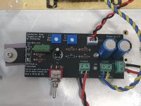
PCB by e_fortier
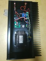
Power supply : 18VDC, 3A SMPS
R1 : 0.5R, 5W https://www.mouser.kr/ProductDetail/Vishay-Draloric/AC05000005007JAC00?qs=R4/Aj8xQbdXW%2BmVd5kK40A==
Inductor : CH-4 (Bel Signal Transformer, 70mH, 600mOhms DCR)
C2, 3 : 3300uF, 25V
When I turn the switch on, the power LED blinks.
Power supply : 18VDC, 3A SMPS
R1 : 0.5R, 5W https://www.mouser.kr/ProductDetail/Vishay-Draloric/AC05000005007JAC00?qs=R4/Aj8xQbdXW%2BmVd5kK40A==
Inductor : CH-4 (Bel Signal Transformer, 70mH, 600mOhms DCR)
C2, 3 : 3300uF, 25V
When I turn the switch on, the power LED blinks.
Attachments
Very likely you have either a short somewhere or the fet is faulty.
Check and re-check again. If you can remove the fet and check for shorts between pins. There should be none.
Check and re-check again. If you can remove the fet and check for shorts between pins. There should be none.
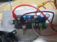
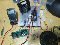
I changed smps to linear psu 17.4VDC.
I turned P1, P2 pots to full counterclockwise.
I switched it up ... then voltage of R1 was about 2.0 VDC.
...and my BOM https://docs.google.com/spreadsheet...XHMWGuYM4kkblgmK2L_q9G52M/edit?usp=drive_link
I turned P1, P2 pots to full counterclockwise.
I switched it up ... then voltage of R1 was about 2.0 VDC.
...and my BOM https://docs.google.com/spreadsheet...XHMWGuYM4kkblgmK2L_q9G52M/edit?usp=drive_link
Attachments
Hi
As I mentioned earlier, P1 is connected the wrong way. You must put it fully clockwise to have minimal bias then turn it gently counterclockwise to slowly increase bias up to about 1.5A to get about 0.75Vdc across R1. Keep me posted.
You can put back your SMPS if you wish.
Eric
As I mentioned earlier, P1 is connected the wrong way. You must put it fully clockwise to have minimal bias then turn it gently counterclockwise to slowly increase bias up to about 1.5A to get about 0.75Vdc across R1. Keep me posted.
You can put back your SMPS if you wish.
Eric
Try starting with the Pots in the middle. It seems like one or both of the pots were "backward" (more voltage is counter clockwise). I can't remember for sure.
@e_fortier Thank you!
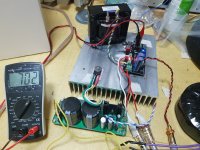
I started adjusting P1 from full clockwise and got 700mV 1.4A bias.
I started adjusting P1 from full clockwise and got 700mV 1.4A bias.
Attachments
Hi
I lent my Zenductor mono blocks to my friend and he’s thrilled with the sound.
He’s got two 24V, 150W power supply so I was wondering which components (if any) would need to be changed for the amp to work at 24V instead of 19V.
Heat dissipation isn’t an issue, heatsink are each 0.45 c/W
The bias is presently set at 19Vdc, 1.5A, would the amps require much higher current at 24Vdc ? 2A maybe ?
The limiting factor now is the choke rated at 35mH, 2A.
I may need to split R1 into 2 resistors, maybe 3W each.
Thanks for your help.
Eric
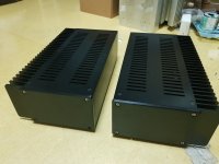
Is that the store mono chassis? Or a different one? How do you like the sound?I've built this amp in mono chassis.
I used MEAN WELL GST60A18-P1J but it made noise so then added CapMx.
https://ko.aliexpress.com/item/1005006872798055.html
I've requested the rear panel as blank to the seller.
You need 2 pcs.
I did not listen with this too much.
I've requested the rear panel as blank to the seller.
You need 2 pcs.
I did not listen with this too much.
What is the required minimal value of C1?
I am considering replacing the 10uf electrolytic capacitor with a smaller value film type capacitor,
I am considering replacing the 10uf electrolytic capacitor with a smaller value film type capacitor,
What value C gives 10 Hz rolloff?
Approximately...
Minimum input Z is 2k,
10 hz x 2pi = 63
63 = 1/RC = 1/(2000 x C)
1/C = 2000 x 63
1/C = 126000
C = 8 uF
Approximately...
Minimum input Z is 2k,
10 hz x 2pi = 63
63 = 1/RC = 1/(2000 x C)
1/C = 2000 x 63
1/C = 126000
C = 8 uF
Thank you so much.
I'm going to use this capacitor.
I think it will be easy to replace since the lead spacing is narrow at 5mm.
I'm going to use this capacitor.
- MKS2B051001N00JO00 : polyester; 10uF; 30VAC; 50VDC; 5mm; ±5%
- https://www.tme.com/kr/en/details/mks2-10u_50v-5%-r/tht-film-capacitors/wima/mks2b051001n00jo00/
I think it will be easy to replace since the lead spacing is narrow at 5mm.
Is this the FET that I should use for the Zenductor:
https://www.digikey.com/en/products/detail/rochester-electronics-llc/IRFP048NPBF/15644563
If not which one do you recommend?
https://www.digikey.com/en/products/detail/rochester-electronics-llc/IRFP048NPBF/15644563
If not which one do you recommend?
It is indeed the IRFP048 but your link seems a bit odd and you wouldn’t be buying directly from Digikey.
The link below is the model directly from digikey:
https://www.digikey.ca/en/products/detail/vishay-siliconix/IRFP048PBF/812764
The link below is the model directly from digikey:
https://www.digikey.ca/en/products/detail/vishay-siliconix/IRFP048PBF/812764
Well, slight, but IMHO significant differences.
Qg and Ciss are important I think.
Infineon's are 89nC / 1900pF,
Vishay 110nC / 2400pF.
Qg, total gate charge will tell you what FR to expect with the idle current current.
Vishay 90kHz, Infineon 112kHz @ 1A.
Qg and Ciss are important I think.
Infineon's are 89nC / 1900pF,
Vishay 110nC / 2400pF.
Qg, total gate charge will tell you what FR to expect with the idle current current.
Vishay 90kHz, Infineon 112kHz @ 1A.
- Home
- Amplifiers
- Pass Labs
- Zenductor