I also didn’t get much gain so I connected my FE2022 and it’s really night and day.

Hi there
Zen amplifier is "evergreen". I remember ryat Nelson once counted the possible permutations oz Zen amp.
So, I was thinking, why not try another one? Being bored a bit by MoFo, I decided to flip it upside down - I conected the transformer between the Drain and + Supply, and then inserted the 0.6 ohm resistor (ok, 8 pieces of 1.2 ohm resistors in parallel/series) between the Source pin and ground.
Of course, the output signal was taken from the Drain. The bias was adjusted to around 1.2 V across the 0.6 ohm resistor, so around 2A (at 19 V supply).
The idea was to get something that resembles an F2, but with an inductor (ok, microwave oven transformer) instead of a constant current source.
I listened to it and it did not sound bad.
Just a bit bright, and had more gain than I like to. Then, I added some negative feedback, but in a watly that was done in the original (1994) Zen. A 22 K resistor from Drain to Gate, and then the bias got re-adjusted by a trimpot from the Gate to ground. I inserted the 2.7 K resistor at the input. I did not want too much feedback because there was already some source degeneration via 0.6 ohm resistor.
I also added a 100 uF capacitor (yeah, an electolytic) at the input (in parallel to the existing 2.2. uF) because the input impedance became much lower now.
I also increased a bias a bit, so now it has 1.5 V across the 0.6 ohm resistor, so 2.5 A bias. The voltage drop across the transformer became a bit more than 4 V (it has slighly less thaj than 2 ohms resistance , as it is a 220V transformer). That leaves 19-4-1.5 = 13.5 V across the Mosfet. At 2.5 A * 13.5 V it dissipated around 34W which is menagable.
Driven by a B1-like buffer, it now sounds very nice.
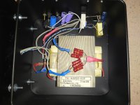
I posted in this thread because it looks very similar to (the rats nest) the Zenductor now, except that the loudspeaker is wired differently. Whether it sounds better or worse than the Zennductor... A question of taste.... 😉
Zen amplifier is "evergreen". I remember ryat Nelson once counted the possible permutations oz Zen amp.
So, I was thinking, why not try another one? Being bored a bit by MoFo, I decided to flip it upside down - I conected the transformer between the Drain and + Supply, and then inserted the 0.6 ohm resistor (ok, 8 pieces of 1.2 ohm resistors in parallel/series) between the Source pin and ground.
Of course, the output signal was taken from the Drain. The bias was adjusted to around 1.2 V across the 0.6 ohm resistor, so around 2A (at 19 V supply).
The idea was to get something that resembles an F2, but with an inductor (ok, microwave oven transformer) instead of a constant current source.
I listened to it and it did not sound bad.
Just a bit bright, and had more gain than I like to. Then, I added some negative feedback, but in a watly that was done in the original (1994) Zen. A 22 K resistor from Drain to Gate, and then the bias got re-adjusted by a trimpot from the Gate to ground. I inserted the 2.7 K resistor at the input. I did not want too much feedback because there was already some source degeneration via 0.6 ohm resistor.
I also added a 100 uF capacitor (yeah, an electolytic) at the input (in parallel to the existing 2.2. uF) because the input impedance became much lower now.
I also increased a bias a bit, so now it has 1.5 V across the 0.6 ohm resistor, so 2.5 A bias. The voltage drop across the transformer became a bit more than 4 V (it has slighly less thaj than 2 ohms resistance , as it is a 220V transformer). That leaves 19-4-1.5 = 13.5 V across the Mosfet. At 2.5 A * 13.5 V it dissipated around 34W which is menagable.
Driven by a B1-like buffer, it now sounds very nice.
I posted in this thread because it looks very similar to (the rats nest) the Zenductor now, except that the loudspeaker is wired differently. Whether it sounds better or worse than the Zennductor... A question of taste.... 😉
Attachments

It theoretically could sound less pleasant as the odd overtone spectrum sims a lot worse than Zenductor, independant of if feedback is adjusted for the same gain. But let your ears decide.
These sound way better than I thought they would. I'm amazed at what kind of sound quality is possible with a few components! Thanks Papa!!
I'm doing maintenance on my Aleph J so I'm listening to the twins connected to my FE 2020. Running at 19.5 volts with a .75 volt bias they amaze me! They are also a good hand warmer.
I'm doing maintenance on my Aleph J so I'm listening to the twins connected to my FE 2020. Running at 19.5 volts with a .75 volt bias they amaze me! They are also a good hand warmer.
Attachments


Last edited:
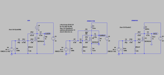
Got curious when I read your post and took your concept one step further. Changed the nfb to the Zenductor values and kept everything as simple as possible. In Zenductor the choke and output cap are in the feedback loop, so it is necessary to have larger values when they are outside. ZENREVIX is what I arrived at.I posted in this thread because it looks very similar to (the rats nest) the Zenductor now, except that the loudspeaker is wired differently. Whether it sounds better or worse than the Zennductor... A question of taste....
Attachments
I have a similar question being based in Australia.Thanks for that Jim and Michael, I notice that is only a 120VAC input model, will look for a universal voltage input model or a 240VAC unit.
According to the data sheet, the Mean Well GST25A12-P1J in standard configuration has the negative not connected to mains FG.
Would that mean this power supply is suitable for the Zenductor amp?
https://www.meanwell.com/productPdf.aspx?i=515#1
You forgot to add a 0.6 ohm source resistor (between the source pin and the ground).Got curious when I read your post and took your concept one step further. Changed the nfb to the Zenductor values and kept everything as simple as possible. In Zenductor the choke and output cap are in the feedback loop, so it is necessary to have larger values when they are outside. ZENREVIX is what I arrived at.
Imagine the original (1994) Zen amp, and make the following changes:
-Power supply: 19 V.
-Put an inductor as the CSS.
-Lower the amount of feedback (If you remember the value of the input resistor of the original Zen was 4K7, just decrease that to 2K2 or 2K7).
-Add 0.6 ohm resistor (10-20w) between the Mosfet source pin and the ground.
Enjoy ! 😉
That is what you did. Unfortunarely you have worsened the performance of both Zen and Zenductor in every respect.Imagine the original (1994) Zen amp, and make the following changes:
-Power supply: 19 V.
-Put an inductor as the CSS.
-Lower the amount of feedback (If you remember the value of the input resistor of the original Zen was 4K7, just decrease that to 2K2 or 2K7).
-Add 0.6 ohm resistor (10-20w) between the Mosfet source pin and the ground.
What I wanted to show you by Zenrevix, was how to maintain the qualities of both.
If you want incorprate the 0.6ohm resistor for a little more temp stabilization, you have to use the earth connections from Zenductor. Otherwise Zout will be very high. Your circuit has a Zout of ca 3.5ohm. If you change your earth connections Zout will be in the ballpark of 1.4ohm. Zen ca 1ohm and Zenductor 0.6ohm(with Rin 4.7k).
About sound quality it is off course up to your ears to decide 🙂 ,
It is exactly what I wanted, a bit higher Zout, (but not too high). For my ears, with a fullrange driver in the open baffle (300Hz and up) it sounds better 😉
I built Zenductor at 2023 Burning Amp, Amp Camp. Want to install on a base and want to include standoffs for support under the heavy inductors. None of my allen wrenches fit the small bolts we used for the standoffs we installed at Amp Camp. Can someone tell me the correct allen wrench size so I can buy a couple? Seems to be a non-standard metric size. Thanks in advance for any help!
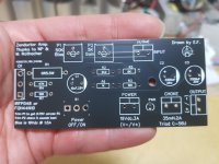
Here we go, revised PCB with proper thanks and Gerbers files for the ones who can’t wait. PCB not tested yet but I’m confident it will work fine. Change R5 for the LED brightness depending on your taste, I’ll change it for a 6K8. Also, this version is slightly more powerful and intended to work with a 19Vdc power supply biased at 1.5A
PCB size made to suit my needs which is an odd heatsink shape with a narrow (52mm) opening…PCB is about 50mm x 100mm max.
View attachment 1258020
Eric
@e_fortier Thank you for sharing the gerber file.
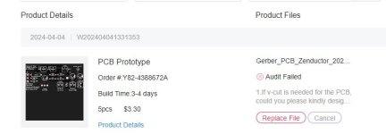
I've ordered PCB with your gerber file but got a email from JLCPCB.
1.If v-cut is needed for the PCB, could you please kindly design no any space or at least 2 mm space between the boards? Or it can not be processed with v-cut.
2.the minimum edge rails we can make is 3mm at least ,could you please kindly enlarge the edge rail in your file to meet our capability ?
I'm sorry but I don't have any skill to modify the gerber file.
Could you edit the gerber file to solve these issues?
Hello
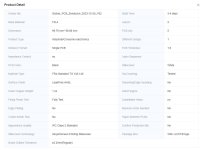
This is very odd, I have ordered these PCB twice and got no questions from JLCPCB.
For the Delivery format option, you have to choose Single PCB. See pic

Please try again.
Eric
This is very odd, I have ordered these PCB twice and got no questions from JLCPCB.
For the Delivery format option, you have to choose Single PCB. See pic
Please try again.
Eric
@e_fortier
I've ordered default option except changing only 'surface finish' to 'LeadFree HASL'.
I will try to order it again.
I've ordered default option except changing only 'surface finish' to 'LeadFree HASL'.
I will try to order it again.
Attachments
@e_fortier
I ordered it without any change with default option.
The new order is in production without any issue.
Thank you!
I ordered it without any change with default option.
The new order is in production without any issue.
Thank you!
@e_fortier
Thank you so much!
Actually, I received a new email about the new order from JLCPCB.
I will try again with this new gerber file.
Thank you so much!
Actually, I received a new email about the new order from JLCPCB.
I will try again with this new gerber file.
Is there any news about a kit or pcb in the store yet?
@Jason Can we expect a Zenductor kit in the diyaudiostore? I would like to build one stereo amp during this winter season.
We are working on it.
Attachments
- Home
- Amplifiers
- Pass Labs
- Zenductor