The PCB ‘feet’ are the hardware to the left. The middle group have slightly longer bolts and kepnuts for mounting the choke to the board.
On the right there are slightly smaller (M3) nuts and bolts for mounting the transistor to the heatsink.
Measure all the resistors and label them!
The trimpots have the value marked, they are 2-digit and multiplier. Where it says “503” this means “50 with three zeroes”, or 50000. Which in electronics would be referred to as 50K. “502” is 50 with two zeroes, 5000, I.E., 5K.
Last edited:

Hi Nelson, just reading the article in post #169 and checking the parts list on page 5, just a few corrections on the QTY table for some items for a pair of boards.
C1 should be qty 2
C2,3 should be qty 4
Inductor mount screw 6-32 x 3/8' should be qty 8
Inductor mount Kepnut 6-32 should be qty 8
PCB mount screw 6-32 x 1/4" should be qty 8 or up to 16
PCB mount standoff 6-32 should be qty 8 or up to 16. Looks like there are 8 mounting holes around the pcb edge.
Thanks for that. As at least one sample kit has shown the correct quantities, but I'll double check what's here in the morning.
Heads up, the nominated on/off switch is already showing nil stock at Digikey - they show a C&K alternative though.
It is very important that you mount the big transistor with the proper order of operations -
1) mount transistor to heatsink as shown, but leave the hardware a little loose. Use a bit of thermal paste Ont he back of the transistor
2) With the transistor attached, solder the heatsink to the PCB.
3) Snug the hardware attaching the transistor.
4) Now solder the transistor leads to the PCB.
Connections. Input from source, out to speaker, power.
Potentiometer P2 should initially be left in it’s midpoint position.
Input. Speaker. Power.
Set meter to DC volts. Probes measure here.
Adjust P1 to 0.5V Small movements have large effects, and it will change as it warms up. Just be patient.
Last edited:
Jim, these pix are so beautiful... and so educative!
They speak for themsemves and say sooo much!
Well chosen, well illustrated... step by step... this is international (even universal should the aliens have the same sight as us LOL) and doesn't even require any text for full understanding.... eventhough it can't of course harm (and helps probably indeed as you did already to make really sure the transistor is mounted correctly).
Whaou!
Thanks as ever for all this, simply excellent!
Claude

Jim, do you have a part number for the 12VDC power supply you show in the build guide pics?
Have found the Meanwell GST60A12-P1J - which is a 5Amp unit - I assume this will suffice?
Have found the Meanwell GST60A12-P1J - which is a 5Amp unit - I assume this will suffice?
Last edited:
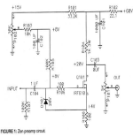
If we find we need a preamp for this what about using our old friend
the Bride of Zen. But speaking of The Bride of Zen it occured to me
that we might simplify it by removing that 8V bias supply and the 100
ohm source resistor and then set the bias with a schade feedback network.
the Bride of Zen. But speaking of The Bride of Zen it occured to me
that we might simplify it by removing that 8V bias supply and the 100
ohm source resistor and then set the bias with a schade feedback network.
Attachments
Getting on the plane. Loooooong day ahead. Early prototypes 🙂

THE GREAT "ZEN-MOD" IS BOTH CLEVER AND RESOURCEFUL!

Thanks Nelson, can I ask if you know whether these pcb's will be available in the store for the many members that cannot be at this years BAF?
Have a great time over the weekend - hope the weather is kind and a good time is had by all who attend.
Have a great time over the weekend - hope the weather is kind and a good time is had by all who attend.
- Home
- Amplifiers
- Pass Labs
- Zenductor