Hi,
Could I use one 'stonger' eg 1000mAh battery for both channels instead of two separate batteris for each channel? Is there any sonic adventage to use separate battery for dedicated channel?
Regards,
B
Could I use one 'stonger' eg 1000mAh battery for both channels instead of two separate batteris for each channel? Is there any sonic adventage to use separate battery for dedicated channel?
Regards,
B
No. Circuit will NOT function
One sets of batteries for each channel.
So 8 sets for 7+1, e.g.
Already explained before.
Patrick
One sets of batteries for each channel.
So 8 sets for 7+1, e.g.
Already explained before.
Patrick
Hi,
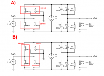
I have got 4x 2Sk146 which I want to use in the SEN topology. For the single channel I will use 2x PCM1704 in parallel. Since 2SK146 is two JFET in one aluminum enclosure I would like to ask how to connect two 2SK146 per channel (A or B from enclosed schematics to better cope with heat dissipation/alignment?
Thanks,
Bern
Attachments

Thanks,
I've measured Idss of my JFETS (2SK146BL). The total of lower and upper pairs of Jfets are 20.6 and 20.7mA for the left channel and 20.62 and 20.72mA respectively for the right channel (see enclosed details). Do you think that 0.1mA Idss mismatch/difference could be an issue? If so how could I limit the adverse impact?
I've build two 10x3.6V (18650) 36V Li-ion battery. Theoretically fully charged single battery should give 42V DC. Do you think that such voltage will be safe for SEN?
TIA,
Bern
Attachments
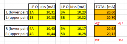
> Do you think that 0.1mA Idss mismatch/difference could be an issue?
Will end up as a small DC at the current input.
> If so how could I limit the adverse impact?
Add a small degeneration resistor to the source of the higher current and trim the DC voltage to Zero at the current input.
> I've build two 10x3.6V (18650) 36V Li-ion battery.
Why would you need 36V ?
Have you calculate how much power you will dissipate, and what is the maximum rating for your FETs ?
Patrick
>
.........
Why would you need 36V ?
Have you calculate how much power you will dissipate, and what is the maximum rating for your FETs ?
Patrick
I have spare, unused 36V batterry from other project which I would like to use in SEN. 🙂
I've read in the LA article:
"...you can go further to 27V or 36V if you wish. The benefit of higher voltage is lower JFET capacitances, which in turn means higher bandwidth and lower distortion."
Roughly I calculate the power of single JFET P=UxI so 36Vx0.01A=0.36W
so maybe for 4 fets should be 1,44W and 1,68W (with max 42V)
For single 2SK146 MAX Gate-Drain Voltage (VGDS) is -40V (as datasheet says) but in SEN schematics there are two Fets in paralell so I assume that I can use max 42V (correct me if I'm wrong).
Thanks
I would not want to run TO92s for more than 60°C at the case.
So you can do a simple experiment to find out how hot they get at 18V Vds at Idss.
Patrick
So you can do a simple experiment to find out how hot they get at 18V Vds at Idss.
Patrick
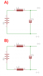
Hi,L = 10mH Fastron 77A series
DCR = 12R
dV ~ 0.5V @ 45mA
C = 10000uF 16V Vishay BC 056 Series
f_RC = 1.3Hz (1st order)
f_LC = 16 Hz (2nd order)
Patrick
As I understood the battery LC filter should looks like on schematics A.
Would be any advantages to use two inductors (see variant B)?
Regards,
Bern
Attachments
I am afraid that these are all design decisions that you have to make yourself.
Cheers,
Patrick
Cheers,
Patrick
.....
> If so how could I limit the adverse impact?
Add a small degeneration resistor to the source of the higher current and trim the DC voltage to Zero at the current input.
....
Hi,
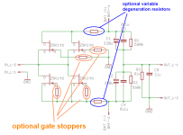
Please have a look on schematic I added OPTIONAL resistors (gate stoppers and degenerate resistors). Is it correct?
I am going use SEN and 2xPCM1704 in parallel per channel.
Regards,
Attachments

Gentlemen (in general and no one in particular),
Many thanks for your interest over the many years; I am truely flattered.
While the SEN / CEN IV look deceptively simple, they are quite complicated to implement and requires good understanding of analogue electronics.
Above all, they require the use of floating power supplies and hence are suspectible to grounding and noise pick-up problems.
If you do not process such skills, I suggest you try something easier for beginners, such as the excellent ZEN IV by Nelson himself.
You will find a lot of details here :
Zen I/V Converter | Pass DIY
Zen I/V Converter
My apologies for not being able to nurse every individual projects to theri successful conclusion.
If you have a technical issue involving the circuit design that has not been addressed before, I am of course interested to know.
Cheers,
Patrick
Just got my hands on 2 pair jfet for the CEN. Does anybody have the board to sell or knows where to get it from?
Cheers!
Cheers!
Sorry i dont understand the circuit completely but for one channel of cen, can i use a single 18v transformer? 0v 18v tap transformer, or do i need 9 0 9? Thanks
Sorry i dont understand the circuit completely but for one channel of cen, can i use a single 18v transformer? 0v 18v tap transformer, or do i need 9 0 9? Thanks
Doenst matter which one you use, as long as it is floating (ie no ground reference on secondary). But transformers may still possibly give you hum problems with this circuit.
JFET current drifts with temperature.
It will drift a lot less when degenerated a lot.
So e.g. if you use 2SK369V and degenrated to 1~2mA, it will be a lot more stable,
then e.g. a 2SK170GR used in the same way.
2Sk209BL or 2SK117BL would also be good choice.
Patrick
What is the recommendation for nulling the offset of a TDA1541 into the SEN where Iout from DAC is unipolor 0 to -4mA?
I've read from other threads using simple resistors 2K2 tied to +5v acting as ccs to source +2mA and using CCS from JFets.
With JFets, is it better to heavily degenerate i.e. 2SK170BL down to 2mA or a BF245A with measured IDSS of 2mA and use at IDSS with slight adjustment at source?
Please excuse the ignorance, I'm trying to understand the concept of which method yields better stability, thanks.
Also, if I were to use a J310 (I know it's obsolete) which data sheet shows IDSS from 24-60mA, would this be even better in terms of heavily degeneration for 2mA?
After 9 years and 2000+ posts, people are still asking for PCBs.
The bad news is that we have none left, and cannot provide JFET sets.
The good news is that we are working on something new along the line of this :
Zen -> Cen -> Sen, evolution of a minimalistic IV Converter
When proven successful, we shall publish in a new thread.
Thank you for your interest,
Patrick
- Home
- Source & Line
- Digital Line Level
- Zen -> Cen -> Sen, evolution of a minimalistic IV Converter