If you make your own PCB, yes.
The pinout of the 2SK146 would have a real hard time fitting onto my PCB.
😉
Patrick
The pinout of the 2SK146 would have a real hard time fitting onto my PCB.
😉
Patrick
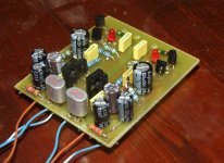
Well, I've built it. The actual SEN is only one tenth of the PCB 😀 , the rest are two shunt regulators. I used two separate transformers, and I was having trouble with large amounts of hum, buzz, distorsion, etc., but that was solved after adding of 100R resistors on gates going to the ground (thanks for the tip  )
)
I still have some "buzz" on higher volume levels, but I thing that the problem is with close proximity of transformers, I will rearrange them. It is sounding good so far, the voltage on regulators is 17.5 V, I will experiment with higher voltages, for with these transformers I can go as high as 21 V regulated.
Thanks again for everything
)I still have some "buzz" on higher volume levels, but I thing that the problem is with close proximity of transformers, I will rearrange them. It is sounding good so far, the voltage on regulators is 17.5 V, I will experiment with higher voltages, for with these transformers I can go as high as 21 V regulated.
Thanks again for everything
Attachments
Ah, once again I forgot to write something.
This is off course only one SEN PCB made for personal use. I do not intend to "manufacture" it or anything like it. It's not even a "real" PCB actualy, I just drilled some more holes in spare space of the shunt PCB and connected the JFETs with wires
This is off course only one SEN PCB made for personal use. I do not intend to "manufacture" it or anything like it. It's not even a "real" PCB actualy, I just drilled some more holes in spare space of the shunt PCB and connected the JFETs with wires
Yes, for such a simple circuit it is really totally viable to do P2P without a PCB.
And I would encourage anyone to try this even on a breadboard.
Suggest you now try to play with passive components, especially R_iv and C_iv.
Don't waste those FETs.
🙂
P.
And I would encourage anyone to try this even on a breadboard.
Suggest you now try to play with passive components, especially R_iv and C_iv.
Don't waste those FETs.
🙂
P.
BTW your SEN circuit is too close to the regulator for my liking.
If you were to do another PCB again, try to separate the two with 5~10mm space.
Just gut feeling, no scientific proof.
Patrick
If you were to do another PCB again, try to separate the two with 5~10mm space.
Just gut feeling, no scientific proof.
Patrick
really? is it simply because its low level analogue? because normally the closer the better, as you well know.
Starting to look at this project again.
Please remind me: Do the SK170's need mathcing of both IDSS and VGS or just IDSS?
Thanks
Ryan
Please remind me: Do the SK170's need mathcing of both IDSS and VGS or just IDSS?
Thanks
Ryan
Patrick, you recommend K170BL for the 8mA IDSS, but I can only source GR at much lower IDSS (3-5mA?). Any ideas on how I can compensate for the lower IDSS?
i'm sure someone can help you find some BL, if nobody closer can, i can probably help you out. is it the standard or sabre version you are building? in other words how many do you need?
Not as is.
Someone has used it successfully for the TDA1541.
Maybe you should ask him.
I have no on-hand experience with those old Philips DACs.
Patrick
Someone has used it successfully for the TDA1541.
Maybe you should ask him.
I have no on-hand experience with those old Philips DACs.
Patrick
- Home
- Source & Line
- Digital Line Level
- Zen -> Cen -> Sen, evolution of a minimalistic IV Converter