My apologies, I discovered I had measured the transformer with the wrong primary ends (inversed). During the previous measurements, the clumped capacitance was higher. Now with the correct wiring it is lower and it results of a -3dB point at 65kHz instead of 58kHz with the secondary grounded. Of course, the square waves show a slightly higher Q factor of the Cp and Ls resonance, this is quite normal.
I will redo these measurements together with the THD measurements and post them when the times comes.
Best regards!
I will redo these measurements together with the THD measurements and post them when the times comes.
Best regards!
Last edited:
These would be perfect for my PP 46 class B amplfier except i would need primary CT 🙂
Well not maybe perfect primary needs to handle 200ma!
Well not maybe perfect primary needs to handle 200ma!
Last edited:
The primary has a natural completely symmetrical CT. It can be used in a P-P configuration. The problem is that you'll have 1.5k of primary impedance per side. It might work for a parallel P-P or a very low Rp tube. 🙂
The primary has a natural completely symmetrical CT. It can be used in a P-P configuration. The problem is that you'll have 1.5k of primary impedance per side. It might work for a parallel P-P or a very low Rp tube. 🙂
it should work ok end to end is 3k?
46 tube data
https://frank.pocnet.net/sheets/021/4/46.pdf
The problem is that you'll have 1.5k of primary impedance per side.
Are you sure?
My bad. I was on a couple of beers when I wrote this post and I still do.
Half of the primary turns results in 1/4 of the primary impedance - 750R.
Using the transformer in a P-P configuration will also lower the Cp, because of the fact the primaries will be referenced to ground from the center tap.
Half of the primary turns results in 1/4 of the primary impedance - 750R.
Using the transformer in a P-P configuration will also lower the Cp, because of the fact the primaries will be referenced to ground from the center tap.
My bad. I was on a couple of beers when I wrote this post and I still do.
Half of the primary turns results in 1/4 of the primary impedance - 750R.
Using the transformer in a P-P configuration will also lower the Cp, because of the fact the primaries will be referenced to ground from the center tap.
I am not as technically inclined I am cornfused

so in a PP plate to plate IMP?
It's a bit more complex actually.
The reflected impedance seen by a PP pair of output tubes depends on more factors, like the operation of the tubes (pentode or triode) and class of operation (class A or (A)B).
The reflected impedance seen by a PP pair of output tubes depends on more factors, like the operation of the tubes (pentode or triode) and class of operation (class A or (A)B).
In the case of the (PP) amplifier working in class A, both tubes are conducting all the time and they swing continuously across the whole secondary. The impedance of the whole secondary is "seen" by both tubes.
But in the case with class B, one tube conducts during a half cycle, while the other does not. So basically one half of the primary works per half of a cycle too. Half the primary will have 4 times less the impedance than the whole primary.
But in the case with class B, one tube conducts during a half cycle, while the other does not. So basically one half of the primary works per half of a cycle too. Half the primary will have 4 times less the impedance than the whole primary.
It's a bit more complex actually.
The reflected impedance seen by a PP pair of output tubes depends on more factors, like the operation of the tubes (pentode or triode) and class of operation (class A or (A)B).
Yes I already told ya class B PP 46 amplifier and there is a link to the data sheet Plate to plate Imp is suggesting 3500ohms or there abouts
I have just started. As I said I am using a EI-120 core.
I have the perfect wire size to wind 2720 primary turns with the selected geometry but don't have the right wire size for 140 secondary turns that will minimize copper loss. So I will use a smaller wire and accepet a bit higher Rdc. Power loss should still be 0.5 dB which is acceptable, I think.
I have the perfect wire size to wind 2720 primary turns with the selected geometry but don't have the right wire size for 140 secondary turns that will minimize copper loss. So I will use a smaller wire and accepet a bit higher Rdc. Power loss should still be 0.5 dB which is acceptable, I think.
yes
if you two gentleman would like an independent listening review on which would sound better I would be obliged🙂
but then the winner would need to wind the other one so i could use them the pair 🙂
if you two gentleman would like an independent listening review on which would sound better I would be obliged🙂
but then the winner would need to wind the other one so i could use them the pair 🙂
I have just started. .
That's great! You'll be probably finished before me. I have to urgently wind the second transformer, because the mandrels will be used by a colleague soon.
if you two gentleman would like an independent listening review on which would sound better I would be obliged🙂
but then the winner would need to wind the other one so i could use them the pair 🙂
A chance I won't be able to see my transformer again. 😀
This gives me an optimistic feeling for my zero experience transformer calculations. For PL519 SE, a mix of tips from Patrick Turner and some inductance meausurement my result was 1920 turns on a 19 sq cm core.
The EI-120 core I am using has a 40x50 sq mm area which is indeed 19 sq cm when considering a typical stacking factor of 0.95.
For 200 Vrms at 20Hz (about 13W into 3K) with low distortion 1920 turns are insufficient because the induction B is way too high for EI cores. They might be ok with Hi-B C-cores.
Winding 2720 primary turns total induction Bdc + Bac (with 130mA DC and 200Vrms signal) is 0.92T at 20Hz. At 30Hz it's even better.
Having more turns means smaller wire size has to be used resulting in a bit higher copper loss however this is still ok with efficiency around 90%. In my experience this is a better choice if high frequency response is good enough.
If one wants better efficiency without compromising other specs better to go with C cores....
That's great! You'll be probably finished before me. I have to urgently wind the second transformer, because the mandrels will be used by a colleague soon.
I am not sure. I have just finished winding the transformer but then need to put the core, impregnate laminations and test it. tomorrow I am going back to UK. I will return back in one month. I don't have any equipment in the UK. I will likely send the OT to my friend Waltube who has certainly better gear to test it thoroughly....
to 45
Ok I am waiting you stuff while I am testing the "strange tubes" 🙂
to 50AE
please use the test set as described on my old post about LITZ trafo ( where I am still running, Hardly!!!).
It is a smart way to test fine the trafos.
You need a good ss amp, 30-50 watt max
You can omit the Ia bias, for now
Walter
Attachments
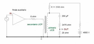
Thank you for suggesting your method. But there is no way I want to test my transformer without Ia. We're testing a transformer for a classic SE application, so there must be current through the primary.
There's no way I can have a 4kV power supply either. A CCS sounds like a much better idea.
There's no way I can have a 4kV power supply either. A CCS sounds like a much better idea.
In my opinion you can test the stuff without Ia first to understand the high frequencies that are impacted not so so heavy by L but parasitic.
For bass without current you can understand the face.
We are check a new method to get the bias current with a better method.
The test on primary winding is more important with a large swing .
Walter
For bass without current you can understand the face.
We are check a new method to get the bias current with a better method.
The test on primary winding is more important with a large swing .
Walter
I'm sorry to hijack the thread, guys where do you buy all the accesories to DIY your own transformers, chokes & OPT in Europe?
- Status
- Not open for further replies.
- Home
- Amplifiers
- Tubes / Valves
- Yet More Discussion on Winding Output Transformers