C-CORE with tow bobbin is gift for people who makes amps for hifi .for last 5 years i buy c-core and winding in tow bobbin. from 10hz to 40khz .
I can do better than that with EI cores or the same for less money....
so i am happy with tow bobbin.why use ei ?
tango is good in distortion and fervency resonance but how abut character in audio ?how abut money ?
Goof for you.
Money is a relative concept.
What is Character? I am not going to start another useless discussion on subjective things.
Breaking up the monotony
ok so I am interested in transformers and have a need for a electrostatic tweeter transformer 5kc and above, I read torroid transformers have very low leakage inductance, and so i wired up a pair primary in parallel, secondary's in series to give the stepup i needed, I then measured the leakage inductance and it was .1mh! so then i measured the FR and it was down by half once i got to 20kc! WTF??
ok so my question for you both what other variable besides leakage inductance defines hi FR?
and since we are dealing with only 5kc and above do we need a magnetic core? since there really is not any low freq to speak of?
Thanks
Lawrence
ok so my question for you both what other variable besides leakage inductance defines hi FR?
I'm none of the two but: interwinding capacitance.
ok so I am interested in transformers and have a need for a electrostatic tweeter transformer 5kc and above, I read torroid transformers have very low leakage inductance, and so i wired up a pair primary in parallel, secondary's in series to give the stepup i needed, I then measured the leakage inductance and it was .1mh! so then i measured the FR and it was down by half once i got to 20kc! WTF??
ok so my question for you both what other variable besides leakage inductance defines hi FR?
Forget general statements and generic claims. The winding geometry is essential. You can have good or bad things regardless of the core type.
The other element is parasitic capacitance. And it's not just abut FR it's also about actual reflected impedence because different ratios of leakage inductance and capacitance can give similar FR but different impedance (as function of frequency). The source impedance also plays a crucial role in all this.
I have never done it so I don't know precisely however I suspect that at 5KHz the core is still having some function, especially those that have low losses that can be "active" up to 10 KHz....and since we are dealing with only 5kc and above do we need a magnetic core? since there really is not any low freq to speak of?
Thanks
Lawrence
Without core you might need to make it bigger (more turns) but air is linear.....
Last edited:
😱😱😱😱😱😱C core transformers have 100% grain oriented cores and the fringing flux around the air gap is near zero if the spacer area is just a tiny bit smaller than the core area. Small practical trick!
You can't design a proper audio transformer ignoring what it does at low frequency! If you use a larger core for core-type transformer to avoid winding more turns then you increase the size which will be worse for both leakage inductance and capacitance.
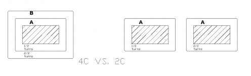
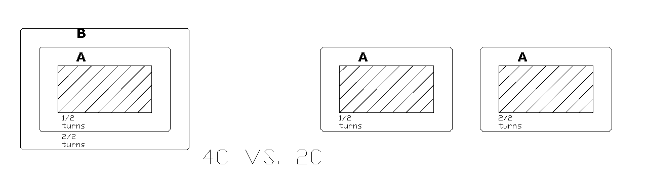
I did give the answer to your question before you asked the question in post n.15!!! Do you know the meaning of vertical and horizontal sectioning?
The reality is the for the 2C using the same basic core number is actually a bit worse. The two coils only cancel partially because the outer parts are too far away and their leakage path goes OUTSIDE the core while the leakage path in 4C core is shorter. This plus the shorter average turn lenght and lower height are not enough to compensate for the additional 41% number of turns (which brings a factor of 2 into the leakage computation). Most manufaturers of high quality audio transformers use the shell type and getting well beyond 100KHz is not a problem. It's not a problem even with EI cores that suffer more leakage.
So please bring this transformer of yours made with 2C's and two bobbins and I will make the equivalent with 4C's. Then we measure them. No practical difference. More copper loss for the 2C type if the basic core is the same. End.
ei transformer 😕
Thanks 45, can you please be more specific on what else matters? from what i keep reading leakage inductance is THE deciding factor for hi Freq performance
I used a Chinese wave generator model numberSGP1010s direct off the generator I did not use in series any resistor to simulate load etc.
I know very little hence the questions
now with what you know about what i need what type kind of transformer should i have wound? I would like 100kc or better topend
Thanks
Lawrence
I think I have already answered several times to your last question: if you have 1920x2=3840 turns on a 2C transformer with a core area A then I only need 2716 with a double core are I get the same inductance, less copper loss and equivalent high frequency performance. If use the same core area with 2C you loose the advantage of size and get worse high frequency performance. If you keep the 1/2 core area and have 2715 turns then your low freuqency performance is A LOT worse. No escape. The shell type transformer is more common for a reason.....
But why? You're just giving a statement, but I need an explanation for that. Or measurements?
Why would, knowing that
The surface area, Ac = 2AC = 4AC
4AC has one bobbin, B with turns Nb
2AC has two bobbins B1 and B2, where the turns Nb1+Nb2=Nb
The core material is the same
The magnetic path length is the same
Why should I need (41%) more to reach the same inductance from 4AC to 2AC? What is the reason? What is the theory behind it?
One good reason the shell type is more common is because there is only one bobbin needed and it's more economical.
Last edited:
Thanks 45, can you please be more specific on what else matters? from what i keep reading leakage inductance is THE deciding factor for hi Freq performance
Leakage inductance, Ls, is in series with the driver and limits HF response due to the increasing reactance vs frequency. It cannot be remedied with a lower impedance drive.
Lumped capacitance, Cp, is in parallel with the driver and is the second evil. It also limits HF response due to shunting reactance. It can be remedied using lower drive impedance, the problem is that it forms a resonance with Ls. The goal towards a well designed transformer is to have this resonance above the audio band. This resonance will also have its Q factor and a high one will cause overshoot.
Primary to secondary capacitance, Cs is not a HF limiter, it helps HF response by capacitive coupling, but you are losing magnetic coupling at higher frequencies.
I've wound an experimental bifiliar tiny 1:1 interstage for DAC output. Bifiliar winding gives extremely low leakage inductance, then vertical sectioning divides the lumped capacitance. Well, this transformer is capable of giving nice square waves up to 10MHz and , but has a 34nF of interwinding capacitance.
Last edited:
ok so I am interested in transformers and have a need for a electrostatic tweeter transformer 5kc and above, I read torroid transformers have very low leakage inductance, and so i wired up a pair primary in parallel, secondary's in series to give the stepup i needed, I then measured the leakage inductance and it was .1mh! so then i measured the FR and it was down by half once i got to 20kc! WTF??
ok so my question for you both what other variable besides leakage inductance defines hi FR?
and since we are dealing with only 5kc and above do we need a magnetic core? since there really is not any low freq to speak of?
Thanks
Lawrence
What size toroid core did you use?
Leakage inductance, Ls, is in series with the driver and limits HF response due to the increasing reactance vs frequency. It cannot be remedied with a lower impedance drive.
Lumped capacitance, Cp, is in parallel with the driver and is the second evil. It also limits HF response due to shunting reactance. It can be remedied using lower drive impedance, the problem is that it forms a resonance with Ls. The goal towards a well designed transformer is to have this resonance above the audio band. This resonance will also have its Q factor and a high one will cause overshoot.
Primary to secondary capacitance, Cs is not a HF limiter, it helps HF response by capacitive coupling, but you are losing magnetic coupling at higher frequencies.
I've wound an experimental bifiliar tiny 1:1 interstage for DAC output. Bifiliar winding gives extremely low leakage inductance, then vertical sectioning divides the lumped capacitance. Well, this transformer is capable of giving nice square waves up to 10MHz and , but has a 34nF of interwinding capacitance.
Thanks, maybe you can help with what I am after
Like i said I need a transformer that will play 5kc up to over 100kc for small electrostatic tweeters RTR ESR-6 for example, Now in electrostatics there is not series inductance, but shunt capacitance and will add with shunt capacitance of the transformer?
when i measured the torroid transformers, this was done without load.
Last edited:
But why? You're just giving a statement, but I need an explanation for that. Or measurements?
Why would, knowing that
The surface area, Ac = 2AC = 4AC
4AC has one bobbin, B with turns Nb
2AC has two bobbins B1 and B2, where the turns Nb1+Nb2=Nb
The core material is the same
The magnetic path is the same
Why should I need (41%) more to reach the same inductance from 4AC to 2AC? What is the reason? What is the theory behind it?
One good reason the shell type is more common is because there is only one bobbin needed and it's more economical.
The inductance is directly proportional to both square turns and core area.
So if you want the same L having 1/2 core area and the same airgap you need more turns: the square of 1.41 is about 2. This is just a gross figure which doesn't take into account other things. Changing the air gap is not generally possible to match it especially when it gets too small. This certainly true for DIY.
However, as the winding volume of the single bobbin for the 4C core is the practically the same as the two bobbins together of the 2C core with 1/2 area and the shorter average turn lenght is not enough to compensate, it is sure the efficiency will be worse for the 2AC if you want the same L, Bmax not reaching saturation, the same DC current, the same high frequency performance.
If you try to get the same efficiency it will be worse in others areas. For example you minimize the space for insulators simplifying the geometry high frequency performance is worse!
If use a bigger 2C core to match the core area it will be worse for the same geometry at high frequency and it is unlikely that with a more complicated geometry (that will require more insulation) it will have the same high frequency performance and maintain the same copper loss at the same time! The latter circumstance will likely depend on the specific case.
Assuming that is possible, why should I do something more complicated if I can get the same same result with less troubles??
The only reason I would do that is I have 2C cores for free and don't look into the horse mouth....
So you make your transformer and I will make mine and will see. Otherwise it ends here.
I would suggest that you learn how a transformer works in all aspects otherwise I think I will win easy....🙂
Last edited:
The inductance is directly proportional to both square turns and core area.
Okay!
So if you want the same L having 1/2 core area and the same airgap you need more turns: the square of 1.41 is about 2.
BUT from the beginning I am trying to say that 2C and 4C will have the SAME core area. 🙁🙁 Why are you insisting on 1/2 core area?!
This is just a gross figure which doesn't take into account other things. For example, the induction is inversely proportional to core area and turns and so in this respect you need actually 2X turns to match the same Bac if you want to maintain the same airgap.
Yes!
However, as the winding volume of the single bobbin for the 4C core is the practically the same as the two bobbins together of the 2C core with 1/2 area and the shorter average turn lenght is not enough to compensate, it is sure the efficiency will be worse for the 2AC if you want the same L, Bmax not reaching saturation, the same DC current, the same high frequency performance.
Why mentioning 1/2 again? The 4C area will be the same as 2C. Do you want a CAD drawing?
If use a bigger 2C core to match the core area it will be worse for the same geometry at high frequency and it is unlikely that with a more complicated geometry (that will require more insulation) it will have the same high frequency performance and maintain the same copper loss at the same time! The latter circumstance will likely depend on the specific case.
Assuming that is possible, why should I do something more complicated if I can get the same same result with less troubles??
The only reason I would do that is I have 2C cores for free and don't look into the horse mouth....
At last we're talking. 2C is finally equal to 4C. Check post 12, where I explained that a single bobbin will have more surface area for the same windings, compared to the splitting into two separate bobbins.
So you make your transformer and I will make mine and will see. Otherwise it ends here.
I would suggest that you learn how a transformer works in all aspects otherwise I think I will win easy....🙂
No worries, I'll make my transformer. 😉 Sooner or later.
Let's see a SE trnasformer. You can start from here:
Bmax = Bdc+Bac = [(L*Idc) + (Vac/4.44*f)]/NAe
with the condition that Bdc>Bac.
4.44 is the form factor for sinusoidal regime, L is the inductance, Idc the max operative DC current, f the (lowest) frequency, N the turns and Ae the effective core area.
So for 1/2 core area you need 2x turns in order to have the same total B, same L, same Idc, same Vac and same f you can't play with the air gap....
Hdc=0.4*pi*N*Idc/Lm
where Lm is magnetic path lenght (which is the same). Having more turns means higher Hdc and that's why the gap cannot be smaller. You can see this looking at real curves of permeability as function of Hdc for different gaps.
So 41% more turns is actually optimistic because not taking into account other things.
Because the winding volume is the same and high frequency performance is equivalent not better as you claim!BUT from the beginning I am trying to say that 2C and 4C will have the SAME core area. 🙁🙁 Why are you insisting on 1/2 core area?!
As I said if you use the same area then for the same geometry high frequancy perfomance is worse for the 2C transformer! The blanket is always too short....
No I can use a commercial split bobbin and redistribute capacitance (if I need) like having two bobbins (and still have the same winding volume as the 2C because for the same core area in reality the 4C has bit more without flange). It is not needed a priori because as I have less turns I can use a simpler geometry for the same leakage inductance and so capacitance is not necessarily worse. Also for less turns I have more space for larger wire and more space for insulators and still can get better efficiency.At last we're talking. 2C is finally equal to 4C. Check post 12, where I explained that a single bobbin will have more surface area for the same windings, compared to the splitting into two separate bobbins.
If they have the same core area the 2C has quite more capacitance and to reach the same result you need even more complicated geometry and will get a bigger transformer for the same job...the blanket again
Last edited:
Edit to previous post: I wrongly wrote "same winding volume as the 2C because for the same core area in reality the 4C"..........it is "same winding volume as the 2C because for 2X core area in reality the 4C"
Phew!!
Don't shoot! I am neutral and venturing out of my shelter - and I do not have a white handkercief to wave; all soiled from wiping away the sweat and battle dust ....
Away from the core area dispute for a minute:
Sk8Ter said;
Not quite; as one increases sections (P-S), intersection capacitance takes over and begins to be the primary h.f. attenuator.
@ 50AE:
Thus as said (and depending on other matters) I generally found that going beyond 3 - 4 secondaries properly placed, the combined effect of Cp and Cs starts dominating (and yes; Cs can help HF response, but depending om where the secondary sections are placed, etc. It also forms a parallel/shunting capacitance: Primary - earth ....... no flame wars on this, please 😱 🙂).
This from experience rather than empirical maths (I am a lazy engineer and relevant factors are difficult to measure anyway. My design procedure is as according to the Crowhurst example, RDH IV pp. 216 - 227). This made me shy away from too much inter-sectioning, following the notion that Ls is all-important.
Your experience please?
Don't shoot! I am neutral and venturing out of my shelter - and I do not have a white handkercief to wave; all soiled from wiping away the sweat and battle dust ....
Away from the core area dispute for a minute:
Sk8Ter said;
.... from what i keep reading leakage inductance is THE deciding factor for hi Freq performance.
Not quite; as one increases sections (P-S), intersection capacitance takes over and begins to be the primary h.f. attenuator.
Leakage inductance, Ls, is in series with the driver and limits HF response .......
-------------------------------------------------------------------------
Lumped capacitance, Cp, is in parallel with the driver and is the second evil. It also limits HF response due to shunting reactance.
-------------------------------------------------------------------------
Primary to secondary capacitance, Cs is not a HF limiter, it helps HF response by capacitive coupling, but you are losing magnetic coupling at higher frequencies.
@ 50AE:
Thus as said (and depending on other matters) I generally found that going beyond 3 - 4 secondaries properly placed, the combined effect of Cp and Cs starts dominating (and yes; Cs can help HF response, but depending om where the secondary sections are placed, etc. It also forms a parallel/shunting capacitance: Primary - earth ....... no flame wars on this, please 😱 🙂).
This from experience rather than empirical maths (I am a lazy engineer and relevant factors are difficult to measure anyway. My design procedure is as according to the Crowhurst example, RDH IV pp. 216 - 227). This made me shy away from too much inter-sectioning, following the notion that Ls is all-important.
Your experience please?
I hope you're not denying that the sum of the surface areas (also resulting in volumes) of A+B is more than than the one of A*2
What is this?? I do not comment on unspecified questions.
Core AD/51 (also known as SG 165/51 or HWR 110/32) with core area of 12.903 cm^2. For each bobbin of the 2C transformer I get 24.9 cm average turn lenght and over 260 cm^2 average surface between interfaces using the full space. The trnasformer size will be 9.5x14x16.5 cm.
If I take the core V51 (also known as SG 89/51 or HWR 50/32) and use 4C's the core area will be 12.904 cm^2. Exactly the same!!!! Then using the full space available as above, the average turn lenght is 24.1 cm and the average surface area 135 cm^2. This core is suitable for a nice low loss 2A3 5W transformer and final size will be about 10x11x12 cm.
The total surface of all interfaces will depend on the final geometry.
And now stop please!!! Make a transformer please!!!!
Last edited:
- Status
- Not open for further replies.
- Home
- Amplifiers
- Tubes / Valves
- Yet More Discussion on Winding Output Transformers