thanks for the advice, but I can easily solder the LT3042/45....🙂 (simple with a small tip soldering iron)
Is it really? Doesn't it have a dissipation plate at the bottom that needs soldering too?
It has. But if you do not have a big output currend and/or voltage drop (= minimal power dissipation) you do not need to solder it. Or: you can make a bigger via under the IC and use a little solder paste befor placing the component. After soldering some pins you can heat the thermal pad from the bottom side.
Nice work kalinowski. Which rpi would you tweak? I did 2B and 2B+ on dual LT3045-1A regs but now i want to Do it on 3+ but there you have 1,2V High current pin for CPU that should have 4A pulse power...
Unsoldering switching regs and connecting to linear is big improvement in terms of get away from digitalisssss ssss sound.
Unsoldering switching regs and connecting to linear is big improvement in terms of get away from digitalisssss ssss sound.
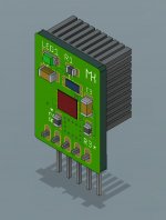
I meant that board should accomodate a heatsink that is dedicated to raspberry pi like this one:
1 Set of Pure Copper Heatsinks 3 Pieces of Heat Sink Cooling Kit for Raspberry Pi 3 Model B-in Demo Board Accessories from Computer & Office on Aliexpress.com | Alibaba Group
🙂
1 Set of Pure Copper Heatsinks 3 Pieces of Heat Sink Cooling Kit for Raspberry Pi 3 Model B-in Demo Board Accessories from Computer & Office on Aliexpress.com | Alibaba Group
🙂
Yes understand but high pulse current for cpu is needed. 1 pcs for 2B or 2B+ is minimal , for 3B+ not enough. They explained that thay lowered voltage form 1.8 to 1,2V and put higher frequency to cpu and bigger current is needed. I dont like that. For audio overclocking is not necessary.
More power to your Pi - Raspberry Pi
More power to your Pi - Raspberry Pi
Hi, nice work, but I'm a little confused with your layout. Do you have maybe some more detailed pictures?
It's a pity it's close to impossible to replace the Raspberry's switching internal regulators for linear ones, as that might be good for the audio quality.
USBridge Sig from ALLO is a motherboard (for the RPi compute module) using onboard linear regulators -
USBridge Sig - Ultra low noise RPI
USBridge Signature Player - Ultra low noise RPI
USBridge Sig - Ultra low noise RPI
USBridge Signature Player - Ultra low noise RPI
It's a pity it's close to impossible to replace the Raspberry's switching internal regulators for linear ones, as that might be good for the audio quality.
The RPi is generating huge amounts of hash in every digital chip, there's little point cleaning up its rails as every load is pumping noise into them, you need separate analog ground and supply rails from the digital ones for analog interfaces.
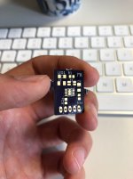
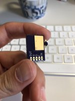
Look what just showed up. OSH park did a shitty job cutting them from the panel so I'll have to fix them up a bit. Other than that, my god, they are tiny!
Hello
How did it go with your lt3045 boards do they work fine?
Best regards
Hello everyone, do you have a schematic and pcb layouts for the lt3042 for the best performance ? should i use a large value cset ? I was warned about low frequency noise if not. But the startup time will be too slow ?
Thank you
Thank you
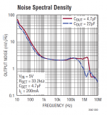
For lowest noise below 100hz you should use 22uF as Cset. However in many applications this is not needed. Fast start capability is described in the datasheet. You only need to add 2 more resistors.
"The optimum load cap for the LT3042 is 4.7uF. Overdoing gets you a noise peak. There is a trace with 22uF."
Low noise regulator for DAC & clock
"The LT3042 wants its 4.7uF output capacitor to have just that value.
Departing in either direction creates noise peaks at high frequencies, but still with an absolute value the others can only dream about."
Mr. Jung's ultra-low noise VREF - the GLED431
Patrick
Low noise regulator for DAC & clock
"The LT3042 wants its 4.7uF output capacitor to have just that value.
Departing in either direction creates noise peaks at high frequencies, but still with an absolute value the others can only dream about."
Mr. Jung's ultra-low noise VREF - the GLED431
Patrick
He had been asking about the Reference bypass cap..
But anyway yes, it is good to keep to a low value, 4,7 /10uF Output bypass capacitor. I use film, PPS.
But anyway yes, it is good to keep to a low value, 4,7 /10uF Output bypass capacitor. I use film, PPS.
Last edited:
Regarding the layouts the evaluation board documentation has valuable information.
https://www.analog.com/media/en/technical-documentation/user-guides/DC2491AF.PDF
https://www.analog.com/media/en/technical-documentation/user-guides/DC2624A_UG-1386.pdf
These are 4-layer boards but 2-layer layout is possible. The LT3094 is a bit tricky in 2-layers because the thermal pad is connected to VIN (i.e. negative input).
For lowest noise below 100hz you should use 22uF as Cset. However in many applications this is not needed. Fast start capability is described in the datasheet. You only need to add 2 more resistors.
That 2 resistors are quite relevant as I found out 🙂
- Home
- Amplifiers
- Power Supplies
- Yet another ultra low noise high PSRR LDO - LT3042