cogitech, I know no more about these amps than you, but here's one more thought that occurred to me:
Following what George and Mr_Zenith said about looking for debris, did you tin (coat with solder) the wire ends that get clamped into the terminals? If not, removing and replacing them could cause strands to beak off inside the terminals. That could be enough to cause a short, I would think. And, you wouldn't see such a tiny strand of wire by looking at the board. And, the problem did seem to arise after re-wiring terminals.
Just a thought... But, hoping you get things worked out soon.
David
Yikes. Certainly a possibility! Now the question is, how the heck do I check? 😕
I'll definitely be tinning the wires (as soon as my roll of solder arrives).
Thanks a lot, David!
Just on the chance, for the U10 CCS, check to make sure there are no solder bridges between the three pins. It's hard to tell from your picture, but it looks a little messy while U20 looks very clean.
The one U10 solder joint is messy but they aren't bridged.
I am thinking I just don't have the knowledge to make this work. Might just pull it apart, cut my losses and sell the parts.
I am thinking I just don't have the knowledge to make this work. Might just pull it apart, cut my losses and sell the parts.
The one U10 solder joint is messy but they aren't bridged.
I am thinking I just don't have the knowledge to make this work. Might just pull it apart, cut my losses and sell the parts.
Hey Cogitech,
I wouldnt do that just yet, that would be shame, you are so close and had it working. My approach is to always try and look back at what you last touched, then take it slow and steady. Your smoked CCS chip is more then likely bad, id get a few of those coming.
I was looking at the photo you posted in post #69
I see two purple wires that looked to be taped up together on your output transformers make sure they are not touching each other. I like to take a wire nut and then place electrical tape on the outside of the wire nut to make sure they are secure.
George mentioned earlier in post #106 to take the choke out of the picture. Im no expert by any means just trying to help if I can. You got this!
Last edited:
Everyone gets Bucked off!!!
Heck Man don't do that, It worked the first time didn't it?? 😀
You have all of the expensive transformers and tubes. Make the next "SSE" out of just "Stock" parts. No screw terminals and such. I just scanned your build thread and noticed you did some mods on the build. I am not a tube amp guy yet but I do like to follow the various build threads. I have built 2 of the Nelson Pass class A amps with great success. I am looking for a tube amp next.
When I was a young kid, I had a crazy "Gelding" horse. I was riding him one day out on the back 40. He saw a "Silver Gum Wrapper" and it spooked him so badly, I flew right over his head. The only way to describe that fall was that, I "busted my ***". I walked him to the barn and my Dad said, "If you don't get on him right now and ride him, that crazy "s.o.b" ain't ever gonna let you ride him. Might have to ride him in the "corral" for a couple of days and keep him reigned in, as we say down here in Loooosiana.
Start at the input power and test your way all the way down the electron path. Be back out there in the Back 40 fore you know it.
And as always a couple of Gin Gimlets for Clarity of Vision always seems to help
Hey Cogitech,
I wouldnt do that just yet, that would be shame, you are so close and had it working. My approach is to always try and look back at what you last touched, then take it slow and steady. Your smoked CCS chip is more then likely bad, id get a few of those coming.
I was looking at the photo you posted in post #69
I see two purple wires that looked to be taped up together on your output transformers make sure they are not touching each other. I like to take a wire nut and then place electrical tape on the outside of the wire nut to make sure they are secure.
George mentioned earlier in post #106 to take the choke out of the picture. Im no expert by any means just trying to help if I can. You got this!
The purple wires were taped well individually before being taped together, and the bare wire ends were cut off - so they definitely aren't touching.
With the obvious short that I discovered based on George's advise to check with the ohmmeter, I have no idea what to do next. I have 4 fuses remaining and don't want to just burn them all up trying things that I don't even understand.
Thanks for your response.
Heck Man don't do that, It worked the first time didn't it?? 😀
You have all of the expensive transformers and tubes. Make the next "SSE" out of just "Stock" parts. No screw terminals and such. I just scanned your build thread and noticed you did some mods on the build.
None of the mods are in place. It's just the basic SSE right now.
I've built several class D amps with great success. Truth be told, I am pretty happy with the way they sound.I am not a tube amp guy yet but I do like to follow the various build threads. I have built 2 of the Nelson Pass class A amps with great success. I am looking for a tube amp next.
When I was a young kid, I had a crazy "Gelding" horse. I was riding him one day out on the back 40. He saw a "Silver Gum Wrapper" and it spooked him so badly, I flew right over his head. The only way to describe that fall was that, I "busted my ***". I walked him to the barn and my Dad said, "If you don't get on him right now and ride him, that crazy "s.o.b" ain't ever gonna let you ride him. Might have to ride him in the "corral" for a couple of days and keep him reigned in, as we say down here in Loooosiana.
Start at the input power and test your way all the way down the electron path. Be back out there in the Back 40 fore you know it.
And as always a couple of Gin Gimlets for Clarity of Vision always seems to help
I just don't have the ability to do any of this without step-by-step instructions and I really don't like playing with high voltage.
It'll probably remain an expensive boat anchor until I part it out.
Sorry for the disappearing act for a couple days. I live 2 miles from a small town in rural West Virginia. The cable internet service here was at or over capacity here before all the frackers came to town, now that they are here, and all inside their temporary housing, it's almost useless. I can type an answer and click "submit" and watch it sit there for a few minutes before a "timeout error" pops up wiping out my submission. My 67 year old fingers are dyslexic on a good day, typing is not easy. I wind up shutting the computer off and walking away before I get angry and break something expensive.
We have a known fault here. It is transient or intermittent such that smoke or steam is produced, but it's origins have not been found. It is likely a simple power supply problem, usually relatively easy to find, not an "it sounds different on Wednesdays" kind of impossible to troubleshoot thing.
It could be as simple as a bad rectifier tube, to an internal transient short in the power transformer. The only known clue in an incorrect ohmmeter reading, and a few things that do not make sense. We know that the problem started when UL was connected, but UL can not cause this, so the problem is likely related to the act of moving things around, or an early component failure. Electronic parts tend to fail in the first 100 hours of use, or after a long period of use, except for tubes, which are like car tires, they wear.
29.2 K ohms is not low enough to blow a fuse, although it might be indicative of a transient breakdown within a part. The fact that it goes UP when you touch is also weird.
I am usually of the "put a fat fuse in it and see what burns mentality," but my projects usually start out with junk box parts, and I'm not afraid of blowing stuff up. That is NOT the popular method of troubleshooting this kind of stuff. A lot of money has been spent here, and a fat fuse can make expensive smoke.
If the amp was here, I would hook up an external current limited power supply that allows forcing power without blowing stuff up, but that's not an option here.....so we must improvise.
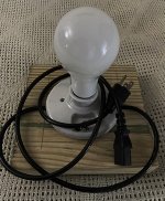
The usual method for hunting down these issues with limited equipment is to make a "dim bulb tester." Simply put you wire an incandescent light bulb in series with the line voltage to the amp. If there is a serious short in the amp the bulb glows brightly, but the fuse does not blow because the bulb absorbs all of the power. If there is no short or excessive current draw, the bulb glows dimly or not at all.
A dim bulb tester can be an elaborate piece of equipment with switches and meters, or it can be simple, a ordinary power cord with it's black wire cut and a 120 volt light bulb socket spliced in series with it.
Make one, connect it in place of the amp's power cord, use a bulb of 60 to 100 watts, connect the amp and apply power with the usual meter on B+. You should see no glow with no tubes installed. There will be a slight glow with only the rectifier tube, until the tube warms and the B+ begins to climb. This is where things went wrong before. As the B+ climbs the bulb should dim, but if the problem still persists it will glow brightly.
If that is still the case, disconnect the choke and repeat. Bulb dim, problem is after the choke. Bulb bright, problem is before choke.
I have 4 fuses remaining and don't want to just burn them all up trying things that I don't even understand
We have a known fault here. It is transient or intermittent such that smoke or steam is produced, but it's origins have not been found. It is likely a simple power supply problem, usually relatively easy to find, not an "it sounds different on Wednesdays" kind of impossible to troubleshoot thing.
It could be as simple as a bad rectifier tube, to an internal transient short in the power transformer. The only known clue in an incorrect ohmmeter reading, and a few things that do not make sense. We know that the problem started when UL was connected, but UL can not cause this, so the problem is likely related to the act of moving things around, or an early component failure. Electronic parts tend to fail in the first 100 hours of use, or after a long period of use, except for tubes, which are like car tires, they wear.
Just ran this test. 29.2 Kohms…. if I touch one of the bolts or heat-sinks with one finger and the top plate with another finger at the same time, the resistance on the ohmeter climbs to 36 Kohms.
29.2 K ohms is not low enough to blow a fuse, although it might be indicative of a transient breakdown within a part. The fact that it goes UP when you touch is also weird.
I am usually of the "put a fat fuse in it and see what burns mentality," but my projects usually start out with junk box parts, and I'm not afraid of blowing stuff up. That is NOT the popular method of troubleshooting this kind of stuff. A lot of money has been spent here, and a fat fuse can make expensive smoke.
If the amp was here, I would hook up an external current limited power supply that allows forcing power without blowing stuff up, but that's not an option here.....so we must improvise.
The usual method for hunting down these issues with limited equipment is to make a "dim bulb tester." Simply put you wire an incandescent light bulb in series with the line voltage to the amp. If there is a serious short in the amp the bulb glows brightly, but the fuse does not blow because the bulb absorbs all of the power. If there is no short or excessive current draw, the bulb glows dimly or not at all.
A dim bulb tester can be an elaborate piece of equipment with switches and meters, or it can be simple, a ordinary power cord with it's black wire cut and a 120 volt light bulb socket spliced in series with it.
Make one, connect it in place of the amp's power cord, use a bulb of 60 to 100 watts, connect the amp and apply power with the usual meter on B+. You should see no glow with no tubes installed. There will be a slight glow with only the rectifier tube, until the tube warms and the B+ begins to climb. This is where things went wrong before. As the B+ climbs the bulb should dim, but if the problem still persists it will glow brightly.
If that is still the case, disconnect the choke and repeat. Bulb dim, problem is after the choke. Bulb bright, problem is before choke.
heres a pretty simple to build dim bulb tester DIY
Dim Bulb Tester Build and How-To | Audiokarma Home Audio Stereo Discussion Forums
Dim Bulb Tester Build and How-To | Audiokarma Home Audio Stereo Discussion Forums
Sorry for the disappearing act for a couple days. I live 2 miles from a small town in rural West Virginia. The cable internet service here was at or over capacity here before all the frackers came to town, now that they are here, and all inside their temporary housing, it's almost useless. I can type an answer and click "submit" and watch it sit there for a few minutes before a "timeout error" pops up wiping out my submission. My 67 year old fingers are dyslexic on a good day, typing is not easy. I wind up shutting the computer off and walking away before I get angry and break something expensive.
We have a known fault here. It is transient or intermittent such that smoke or steam is produced, but it's origins have not been found. It is likely a simple power supply problem, usually relatively easy to find, not an "it sounds different on Wednesdays" kind of impossible to troubleshoot thing.
It could be as simple as a bad rectifier tube, to an internal transient short in the power transformer. The only known clue in an incorrect ohmmeter reading, and a few things that do not make sense. We know that the problem started when UL was connected, but UL can not cause this, so the problem is likely related to the act of moving things around, or an early component failure. Electronic parts tend to fail in the first 100 hours of use, or after a long period of use, except for tubes, which are like car tires, they wear.
29.2 K ohms is not low enough to blow a fuse, although it might be indicative of a transient breakdown within a part. The fact that it goes UP when you touch is also weird.
I am usually of the "put a fat fuse in it and see what burns mentality," but my projects usually start out with junk box parts, and I'm not afraid of blowing stuff up. That is NOT the popular method of troubleshooting this kind of stuff. A lot of money has been spent here, and a fat fuse can make expensive smoke.
If the amp was here, I would hook up an external current limited power supply that allows forcing power without blowing stuff up, but that's not an option here.....so we must improvise.
The usual method for hunting down these issues with limited equipment is to make a "dim bulb tester." Simply put you wire an incandescent light bulb in series with the line voltage to the amp. If there is a serious short in the amp the bulb glows brightly, but the fuse does not blow because the bulb absorbs all of the power. If there is no short or excessive current draw, the bulb glows dimly or not at all.
A dim bulb tester can be an elaborate piece of equipment with switches and meters, or it can be simple, a ordinary power cord with it's black wire cut and a 120 volt light bulb socket spliced in series with it.
Make one, connect it in place of the amp's power cord, use a bulb of 60 to 100 watts, connect the amp and apply power with the usual meter on B+. You should see no glow with no tubes installed. There will be a slight glow with only the rectifier tube, until the tube warms and the B+ begins to climb. This is where things went wrong before. As the B+ climbs the bulb should dim, but if the problem still persists it will glow brightly.
If that is still the case, disconnect the choke and repeat. Bulb dim, problem is after the choke. Bulb bright, problem is before choke.
Hi George. Thanks for the advise. I will build myself a dim bulb tester and proceed with the tests.
Perhaps I can offer the following tip to help reduce your internet frustrations if you are having intermittent connectivity issues. After typing a very long and detailed response (like the one above) but before clicking "submit reply" select all your text and then copy and paste it into wordpad or whatever text editor you use. Then submit your reply. If the connection times out at that very time, you can simply copy and paste your response in and try again. In fact pasting into wordpad is not even necessary because the text will be in your clipboard, but it might make you feel better to see it get pasted into wordpad. You probably already know this, and I don't mean to be condescending in the least. I just know how frustrating it can be when that happens.
heres a pretty simple to build dim bulb tester DIY
Dim Bulb Tester Build and How-To | Audiokarma Home Audio Stereo Discussion Forums
Thanks for the link. That's a very nice setup and easy enough to build, but I think I'll do the quick n' dirty light socket wired into a power cord as George mentioned. I've got lots of extra power cords jammed in boxes from all the PC power supplies I've had over the years. Remote switch will be a power bar.
Amp Repair
Come on Cogitech, I am running out of beer waiting for you to get your amp repaired.😀😀
Come on Cogitech, I am running out of beer waiting for you to get your amp repaired.😀😀

Hey guys, I literally haven't touched it since my last attempt. I exceeded the "WAF" in my house during the build, and now that it doesn't work I need to give it a few weeks before I dare divert my attention back to the amp.
I did round up the parts for a dim-bulb tester (paid $7 for two 100w incandescent bulbs, FFS!) and hope to put it together on the weekend.
I did round up the parts for a dim-bulb tester (paid $7 for two 100w incandescent bulbs, FFS!) and hope to put it together on the weekend.
I exceeded the "WAF" in my house during the build
I kinda violated that one too spending two days making an UNSET test board, 2 more days populating and testing it, and another day taking measurements.
So I got this new amp running and since we are confined to the house, I can't hook up some speakers and turn it to 11.
I finally had a few hours to tinker today. Here's what I accomplished:
- Removed the board and inspected all components with my magnifying visor on - did not discover anything new
- Inspected the inside of all the terminal blocks to look for broken stands of wire - nothing found
- Tinned the ends of all the wires that terminate in terminal blocks, to prevent strands of wire breaking off in the future
- Re-installed the board and connected everything up
- Built my dim-bulb tester
I have just re-run this test and the results are now different:
- With the choke connected, the resistance is 52.5K ohms
- With the choke disconnected, the resistance is 156K ohms (I ran this test just out of curiosity and I don't understand why the results are so different, but hopefully it is a clue that someone else will understand)
I am completely confused by these results but I am glad the reading with choke connected is at least higher than it was when I tested before (~29K ohms).
I decided not to even try powering up with the dim-bulb tester until I get some more feedback on these test results.
- Removed the board and inspected all components with my magnifying visor on - did not discover anything new
- Inspected the inside of all the terminal blocks to look for broken stands of wire - nothing found
- Tinned the ends of all the wires that terminate in terminal blocks, to prevent strands of wire breaking off in the future
- Re-installed the board and connected everything up
- Built my dim-bulb tester
With no power to the board connect an ohmmeter between the B+ (R4 is fine) and ground (like when the B+ voltage was measured, only set to ohms). It will take a minute or so, but the reading should settle to around 75K ohms. My SSE measures 74.2K ohms. A low reading indicates a short somewhere. If the reading is around 75K flex the board in the area where the CCS chips are to see if the reading changes.
I have just re-run this test and the results are now different:
- With the choke connected, the resistance is 52.5K ohms
- With the choke disconnected, the resistance is 156K ohms (I ran this test just out of curiosity and I don't understand why the results are so different, but hopefully it is a clue that someone else will understand)
I am completely confused by these results but I am glad the reading with choke connected is at least higher than it was when I tested before (~29K ohms).
I decided not to even try powering up with the dim-bulb tester until I get some more feedback on these test results.
Atta Boy
I am glad to see you back on your amp repair.
I Don't know what "WAF" stands for but I am sure I have committed that crime in my 22 years of Marriage.
Easier to Beg for forgiveness than ask for permission.
I am glad to see you back on your amp repair.
I Don't know what "WAF" stands for but I am sure I have committed that crime in my 22 years of Marriage.
Easier to Beg for forgiveness than ask for permission.
Easier to Beg for forgiveness than ask for permission.
Perfect timing for this quote!! I brought home a set of cornscalas a few days ago to replace a set of fortes and the girlfriend was not a happy camper...😀
- Home
- More Vendors...
- Tubelab
- Yet Another SSE Build Thread