Blown CCS?
OK, well that didn't take long.
Rectifier only test, DMM hooked up to test B+, remote power switch, just as George prescribed.
B+ got up to maybe 30 volts, the rectifier tube lit up normally, and then I heard a short, quiet vvvvhhhnt (you know, that sound of current, like in a seized electric motor?) and immediately looked at the board.
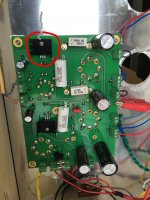
A small stream/puff of smoke came from the CSS (see attached). Actually, I am not 100% sure. It may have come from the other side of the board...
I shut it down with the remote switch and stood there for a minute or two, thinking. I then went ahead and flipped the remote switch on again.
No B+ at all. I waited 15 or 20 seconds and then shut it down again.
So that's where it stands right now.
I used these CCS chips: IXCP10M45S IXYS | Mouser Canada
OK, well that didn't take long.
Rectifier only test, DMM hooked up to test B+, remote power switch, just as George prescribed.
B+ got up to maybe 30 volts, the rectifier tube lit up normally, and then I heard a short, quiet vvvvhhhnt (you know, that sound of current, like in a seized electric motor?) and immediately looked at the board.
A small stream/puff of smoke came from the CSS (see attached). Actually, I am not 100% sure. It may have come from the other side of the board...
I shut it down with the remote switch and stood there for a minute or two, thinking. I then went ahead and flipped the remote switch on again.
No B+ at all. I waited 15 or 20 seconds and then shut it down again.
So that's where it stands right now.
I used these CCS chips: IXCP10M45S IXYS | Mouser Canada
Attachments
Last edited:
Hey, you're making progress. And a lot of extra credit for the "smoke", which was totally awesome. I don't recall ever seeing anyone do that before, and it does help us visual types. So... regardless of what actually poofed, I'll place my bets now that George's next question would be, "So what made it smoke?"
It's more than likely that there are several possible causes, but George is much better qualified to weigh in on those. In the meantime I'd do another visual, then (assuming it's the CCS) measure several of the components surrounding it to verify whether or not any of those other components were affected (again, assuming U10 blew then I'd measure R13, R14 and R19).
Hopefully you have one or two spare ICs, but if not I wouldn't worry about that until you ascertain the root cause.
Another thought: when you flipped the switch the second time (when there was no B+), were you able to determine if the heaters were lit? And did the fuse blow?
And another another thought: if the smoke did originate from the "far" side of the board, then just about every component in that vertical line is still suspect, including the other CCS. And if it is indeed one of the CCS chips then something other than a tube is completing its path to either ground or some other lower voltage point.
Last edited:
When I flipped the switch the second time, I didn't check anything except B+ and I looked for more smoke. There was no action at all.
I should check the fuse...
BTW I do recall George writing somewhere about big problems with certain recent-production CCS chips from IXYS frying in the SSE. I had already ordered mine when I read it. I am guessing they are the exact ones that I bought, but I will wait for George to confirm that.
I should check the fuse...
BTW I do recall George writing somewhere about big problems with certain recent-production CCS chips from IXYS frying in the SSE. I had already ordered mine when I read it. I am guessing they are the exact ones that I bought, but I will wait for George to confirm that.
I should check the fuse...
First check the fuse. If there is no B+ and the rectifier tube is not lighting up, the fuse is likely dead.
I have seen the CCS chips blow, but rarely in an SSE, in fact I can't remember seeing a dead one in an SSE since there is a resistor between the CCS chip and B+. Look at R14 and R24 for any signs of damage. If none is found remove the heat sink and look at the plastic part of the CCS chip. If smoke happened, it should be obvious.
Your comment about bad IXYS parts brings me to the FRED diodes, D1 and D2. If you are not planning on using the solid state rectifier option, just remove them. The IXYS parts were prone to failure on power surges. A dead one will blow fuses and cause no B+. They are not used unless the solid state rectifier switch is installed, but a bad one can cause problems.
The fuse is dead.
I will need to remove the board from the chassis to inspect R14/24. Is there anything else I should try/test before removing the board for inspection purposes (just to save myself some time)?
When I remove the board, I'll remove the FREDs. I thought I would have fun playing with SS vs. tube rectification, but I just want the amp to work now. 🙂
Last edited:
Is there anything else I should try
The CCS chip could be fried into a lump of carbon (highly unlikely/nearly impossible) and there would not be enough current flow to blow a fuse. There is a major issue somewhere that is not obvious yet.
There is a short, or intermittent short, somewhere on the B+ circuit that is strong enough to blow the fuse. You could divide the problem in half by disconnecting the choke and powering it up again with the rectifier tube installed. If the fuse does not blow, the problem is after the choke. If the fuse still blows, the problem is the rectifier tube, C1, the FRED diodes, or the wiring. Without the choke, there will be no voltage on C4 so connecting a meter is not necessary. There will be voltage on the choke connector pin closest to the rectifier tube if you want to measure B+.
Is it possible that one of the components (or the screw for the CCS chip) on the other side of the board is up high enough to touch the top plate?
With no power to the board connect an ohmmeter between the B+ (R4 is fine) and ground (like when the B+ voltage was measured, only set to ohms). It will take a minute or so, but the reading should settle to around 75K ohms. My SSE measures 74.2K ohms. A low reading indicates a short somewhere. If the reading is around 75K flex the board in the area where the CCS chips are to see if the reading changes.
I will need to remove the board from the chassis
If the board is removed carefully examine any area where something might have touched the top plate for signs of a spark mark.
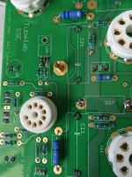
Went ahead and removed the board. No signs of damage to R14 or R24 (see attached). No signs of damage to any resistors, actually.
I lifted U10 slightly (bent the pins just a bit) to get a look at the CCS plastic. No obvious signs of melting or burning. I should note that I used heat-sink compound (the common white stuff) when I installed the heat-sinks on the CCS parts. Could it have been boiling/burning?
I have removed the FREDs by simply clipping their leads close to the board surface. Is there any harm in leaving them this way?
Attachments
I was away working on this while you were posting that last message George. I am starting to get confused now...
I see no signs of spark marks on the top plate, and nothing that I can see that would come close to the top plate when the board is installed.
I'll have to read through your last post carefully and figure out what I need to do next.
I see no signs of spark marks on the top plate, and nothing that I can see that would come close to the top plate when the board is installed.
I'll have to read through your last post carefully and figure out what I need to do next.
Last edited:
With no power to the board connect an ohmmeter between the B+ (R4 is fine) and ground (like when the B+ voltage was measured, only set to ohms). It will take a minute or so, but the reading should settle to around 75K ohms. My SSE measures 74.2K ohms. A low reading indicates a short somewhere. If the reading is around 75K flex the board in the area where the CCS chips are to see if the reading changes.
OK I am going to re-install the board and run this test. I'll have to do it a bit later...
I should note that I used heat-sink compound (the common white stuff) when I installed the heat-sinks on the CCS parts. Could it have been boiling/burning?
I have removed the FREDs by simply clipping their leads close to the board surface. Is there any harm in leaving them this way?
I seriously doubt that the ICs could have cooked the heatsink compound without at least some visible damage to the ICs themselves. And the clipped FRED leads are absolutely fine provided there's sufficient space between the clipped leads and the amp top plate.
Last edited:
Thanks Mr_Zenith. I've been delayed by (socially distanced) guests since the last post and been into the whiskey a bit, so I am going to have to resume the troubleshooting tomorrow afternoon...
That's okay, I understand completely. Just cooked up a batch of simple syrup, myself. Deciding on what to mix it with now... 😀
With no power to the board connect an ohmmeter between the B+ (R4 is fine) and ground (like when the B+ voltage was measured, only set to ohms). It will take a minute or so, but the reading should settle to around 75K ohms. My SSE measures 74.2K ohms. A low reading indicates a short somewhere. If the reading is around 75K flex the board in the area where the CCS chips are to see if the reading changes.
Just ran this test.
29.2 Kohms. I wish I knew what to do next, without having to ask for every step - but I don't.
I also just realized my choke chassis isn't grounded. I'll need to deal with that.
Another thing I am curious about: Are the CCS chip bolt holes in the PCB only there for mechanical reasons or are they electrically significant? My bolts didn't line up with the holes when I installed the CCS chips, so the bolts are not connected to the board. The reason I ask is because if I touch one of the bolts or heat-sinks with one finger and the top plate with another finger at the same time, the resistance on the ohmeter climbs to 36 Kohms.
Last edited:
Wow, there's definitely something going on. George is much better at "tele-shooting" than I am, his being the circuit designer notwithstanding. Let me look at the schematic. I will say that if memory serves, it stands to reason that touching the heatsinks would alter the resistance reading since the they're at B+ during normal operation.
BTW: the gin gimlet was awesome, but alas, no cucumber for the garnish. Thanks for the suggestion! 😀
BTW: the gin gimlet was awesome, but alas, no cucumber for the garnish. Thanks for the suggestion! 😀
Hey Cogitech,
Sorry to hear all of the hassles you have encountered. Just been reading up on your thread here. I wish I had some good advice for you. Only thing I can say is to really visually go over the board well and make sure there isnt something small your missing.
When messing around with my amp the other day I was getting sound without the speakers connected!! Took me a few hrs, had a few beers staring at it, and noticed a very fine wire grounding out on the chassis.
Did you ever try this what George mentioned:
Not even sure if this is a good idea with the smoke you saw earlier, id wait and see what George recomends sounds like a good way to help isolate everything.
There is a short, or intermittent short, somewhere on the B+ circuit that is strong enough to blow the fuse. You could divide the problem in half by disconnecting the choke and powering it up again with the rectifier tube installed. If the fuse does not blow, the problem is after the choke. If the fuse still blows, the problem is the rectifier tube, C1, the FRED diodes, or the wiring. Without the choke, there will be no voltage on C4 so connecting a meter is not necessary. There will be voltage on the choke connector pin closest to the rectifier tube if you want to measure B+.
Hey thanks guys. What I don't get is how the hell the amp played perfectly for 2 days in triode, then I switched to UL mode and ... this?
I'll wait for George to read my update a few posts back and recommend a next move. I am not in a rush to get this solved. Better to take it slow and figure it out for good.
I'll wait for George to read my update a few posts back and recommend a next move. I am not in a rush to get this solved. Better to take it slow and figure it out for good.
No sweat. I know it's weird to you now, but it happens all the time. And again I can almost promise you it's some tiny, stupid thing that was overlooked, like a cut-off resistor lead bridging some contacts or a solder bridge that went unnoticed. We've all had it happen at some point. Even Alan Shepard nearly fell victim to what is believed to be a solder ball rolling around in the LEM's computer during the Apollo 14 landing.
In November I took my Tubelab SE-II (which had been working perfectly for months) to Burning Amp 2019. It worked wonderfully all day until one of the channels went dead during the last afternoon audition. Thinking it was something simple we jiggled the input leads and the dead channel sprang to life. We chalked it up to a bad cable and left it at that.
But... the problem continued after returning home. It drove me nuts; surely it couldn't be another cable?! It wasn't - it was a defective input jack, a brand-new Neutrik no less! That possibility had never occurred to me since I'd never even had a cheap-o Radio Shaft jack fail before. Go figure.
So... until you hear back from George I would suggest doing a few simple things by way of elimination, like:
- Checking your coupling caps for shorts (they should read open on an ohmmeter)
- Verifying there are no primary-to-secondary shorts in your output transformers (again they should read open)
- To the extent that you can, checking for solder bridges or other debris that could be making some unsavory contacts. That includes the tube sockets.
Last edited:
So... until you hear back from George I would suggest doing a few simple things by way of elimination, like:
That way you'll confirm for sure whether or not the root cause lies somewhere in the board itself. With a little more work I'm sure you'll be back in business soon!
- Checking your coupling caps for shorts (they should read open on an ohmmeter)
- Verifying there are no primary-to-secondary shorts in your output transformers (again they should read open)
- To the extent that you can, checking for solder bridges or other debris that could be making some unsavory contacts. That includes the tube sockets.
While I truly appreciate everyone's effort to help me, I think it is important for me to continue to explain how little I actually know. For example:
- I have no idea what coupling caps are (actually, I could guess, but I might be wrong). If I could figure that out, do I need to remove them from the board to test them?
- For testing primary to secondary shorts in the OPTs, do I connect one ohmmeter lead to one of the primary leads and then systematically connect the other ohmmeter lead to each secondary lead, and then move on to the next primary lead and again test all the secondary leads, and so on?
- I have really gone over the board several times wearing my Donegan Optical magnifying visor and I have not noticed anything odd, but my experience with finding faults is very limited. Everything looks the same to me as the day I soldered it. I'll go over it again systematically and do my best. I think I will wait till tomorrow.
cogitech, I know no more about these amps than you, but here's one more thought that occurred to me:
Following what George and Mr_Zenith said about looking for debris, did you tin (coat with solder) the wire ends that get clamped into the terminals? If not, removing and replacing them could cause strands to beak off inside the terminals. That could be enough to cause a short, I would think. And, you wouldn't see such a tiny strand of wire by looking at the board. And, the problem did seem to arise after re-wiring terminals.
Just a thought... But, hoping you get things worked out soon.
David
- Home
- More Vendors...
- Tubelab
- Yet Another SSE Build Thread