Yes, but the simulations are for only one 3 mm wide aluminium strip.
If you have wider strips perhaps divided into two or three, the gap distance really doesn't matter.
It'll be a sub-optimization.
If you have wider strips perhaps divided into two or three, the gap distance really doesn't matter.
It'll be a sub-optimization.
For what it is worth, here's some measurements without anh with some "waveguides":

SPL:

The bottom is without the waveguide and the two at top is with.
Nothing much, perhaps 1 dB over the spectrum.
Distortion:

Now this is something different, almost 5 dB lower 2HD distortion in the low end 250 to 300 Hz.
Clearly something that needs more investigation.
Higher HDs doesn't show any differencies
SPL:
The bottom is without the waveguide and the two at top is with.
Nothing much, perhaps 1 dB over the spectrum.
Distortion:
Now this is something different, almost 5 dB lower 2HD distortion in the low end 250 to 300 Hz.
Clearly something that needs more investigation.
Higher HDs doesn't show any differencies
Last edited:

When testing a faily wide baffle keep in mind that the front response only tells half the story. I think you should also measure the off axis response, 0-90 degrees from 0.5 - 1 m and see if both options perform equally there too.
As a disclaimer before: The following measurements are with a single 9 cm tall driver. Since you will build a 220 cm tall driver then while you will still have these problems you only have them in the horizontal direction and not the vertical, so the effect is smaller. Hence why it would be interesting to see if it is an actual problem in your current waveguided prototype or just a theoretical problem.
Data to show potential problems of wide baffles for dipoles:
Here is one of my previous measurements of a PT2522 in a ~ 30 cm wide rounded baffle / waveguide.

The important thing to notice is that the 750 hz dip and overtone dips are not uniform off axis until the frequency is small enough that it is controlled by the waveguide. This is why it is popular to instead go for minimal baffles which measures like this:

But they are less efficient on the low end. Also note that annoyingly the PT2522 has a hard baffle that is too wide relative to its radiating area so we get a dipole peak in the 7-8 khz range which isn't nice.
And lastly, if you get a problem with the dipole peak and you want to mitigate it then instead of going with a minimal baffle you can go the other way: make the baffle large enough to control dispersion down to 300-400 hz but that would be a large baffle indeed 😆
As a disclaimer before: The following measurements are with a single 9 cm tall driver. Since you will build a 220 cm tall driver then while you will still have these problems you only have them in the horizontal direction and not the vertical, so the effect is smaller. Hence why it would be interesting to see if it is an actual problem in your current waveguided prototype or just a theoretical problem.
Data to show potential problems of wide baffles for dipoles:
Here is one of my previous measurements of a PT2522 in a ~ 30 cm wide rounded baffle / waveguide.
The important thing to notice is that the 750 hz dip and overtone dips are not uniform off axis until the frequency is small enough that it is controlled by the waveguide. This is why it is popular to instead go for minimal baffles which measures like this:
But they are less efficient on the low end. Also note that annoyingly the PT2522 has a hard baffle that is too wide relative to its radiating area so we get a dipole peak in the 7-8 khz range which isn't nice.
And lastly, if you get a problem with the dipole peak and you want to mitigate it then instead of going with a minimal baffle you can go the other way: make the baffle large enough to control dispersion down to 300-400 hz but that would be a large baffle indeed 😆
Last edited:
Thanks for your input, OllBoll.
I've also gone from a wide baffle to a minimum baffle and back, but in the end I have always thought that the minimum baffle is the best approach.
A decrease the 2HD distortion level could mean that I can cutoff lower or keep the cutoff frequency with a lower order.
So this was just a quick test; the printer did most of the job.
I have tested without the waveguide but with three ridges as in the picture above or seven ridges:

But there no significant changes.
I then straightened the corrugation:


So the corrugation is definitely needed!
Then there's the cut-off frequency between the mid and the tweeter.
For dispersion reasons, as far as I know, you shouldn't cut off higher than the frequency that correspond to λ/4 of the cc-distance of the two elements.
And with the current design that frequency will be a little bit on the low side for my liking.
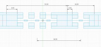
So how can I put the elements closer together?
Here's on suggestion:

With 42.5 mm I would get 2024 Hz as the highest cut-off frequency.
Do I need to worry about how the rightmost mid opening is that close to the tweeter extension?
I use Roon's DSP to get the necessary delay of the tweeter.
But there no significant changes.
I then straightened the corrugation:
So the corrugation is definitely needed!
Then there's the cut-off frequency between the mid and the tweeter.
For dispersion reasons, as far as I know, you shouldn't cut off higher than the frequency that correspond to λ/4 of the cc-distance of the two elements.
And with the current design that frequency will be a little bit on the low side for my liking.
So how can I put the elements closer together?
Here's on suggestion:
With 42.5 mm I would get 2024 Hz as the highest cut-off frequency.
Do I need to worry about how the rightmost mid opening is that close to the tweeter extension?
I use Roon's DSP to get the necessary delay of the tweeter.
Are the distortion measurements of corrugated vs not of the exact measurements above or are they SPL normalized over the whole range? As in does the corrugated membrane have 10 dB more SPL @ 300 hz at the same time as it has 6 dB less distortion?
Interesting that not only does corrugation massively improve the low end response but that the high end isn't impacted negatively either. I guess the only downside is that the mechanical xmax is reduced but I'd much rather have a lower effective xmax but with actual good performance than a higher theoretical but where the low end distortion is so high it is just a bad idea to actually use the xmax.
If you decide you want better high end response than provided by the 5 magnet row driver I suggest you skip the 5 row driver and just make the 3 row midtweeter. You'd have to cross higher at say 400-500 hz but still low enough you don't get crossover problems. Crossing at 1-2 khz is not ideal since it is smack in the middle of where the ear is the most sensitive. And since they are beside each other you can't time align properly at 2 khz since then either the left or the right off axis response will be wrong. The usual hack of placing the drivers on top of each other doesn't work here on arrays.
But in the end with 5 magnet rows of 5 mm magnet width, 5 mm gap you have a radiating area of 35 mm wide. Basically the same as a BG Neo3W / Clone. Sure you can get better high end dispersion but do you really need it? Isn't the dispersion enough?
Here is a GR Neo3 which is a clone of the Neo3W. 5 rows of magnets. The PDRWool is the same but with the 2 outer rows covered with wool felt carpet, improves the top end slightly.
Last edited:
The measurements are SPL normalized (dBr). I find that they are much easier to evaluate.
Here are the same measurements with no normalization:


It's even harder to make something out of the overlay:

Here are the same measurements with no normalization:
It's even harder to make something out of the overlay:
Last edited:
Yes, corrugation it is!Interesting that not only does corrugation massively improve the low end response but that the high end isn't impacted negatively either. I guess the only downside is that the mechanical xmax is reduced but I'd much rather have a lower effective xmax but with actual good performance than a higher theoretical but where the low end distortion is so high it is just a bad idea to actually use the xmax.
I can cut off at 500 Hz but it'll really push the base (AE TD15H) drivers to their limit; I would rather prefer to have the cut off at 300 Hz.If you decide you want better high end response than provided by the 5 magnet row driver I suggest you skip the 5 row driver and just make the 3 row midtweeter. You'd have to cross higher at say 400-500 hz but still low enough you don't get crossover problems. Crossing at 1-2 khz is not ideal since it is smack in the middle of where the ear is the most sensitive. And since they are beside each other you can't time align properly at 2 khz since then either the left or the right off axis response will be wrong. The usual hack of placing the drivers on top of each other doesn't work here on arrays.
And the next cut off around 3000 Hz that could be feasible (λ/3 instead of λ/4) with the above suggestion.
The finished speakers will be each other's mirror image. I don't understand why the time alignment should be a problem, could you elaborate a bit?
I think a 35 mm wide tweeter doesn't have the desired dispersion.But in the end with 5 magnet rows of 5 mm magnet width, 5 mm gap you have a radiating area of 35 mm wide. Basically the same as a BG Neo3W / Clone. Sure you can get better high end dispersion but do you really need it? Isn't the dispersion enough?
Sorry, I cannot see the improvement on the PDRWool high end; it is about 5 dB lower.Here is a GR Neo3 which is a clone of the Neo3W. 5 rows of magnets. The PDRWool is the same but with the 2 outer rows covered with wool felt carpet, improves the top end slightly.
View attachment 1327710 View attachment 1327711
Remember that I intend to EQ any positive bump but no negative.
Gladly.The finished speakers will be each other's mirror image. I don't understand why the time alignment should be a problem, could you elaborate a bit?
The problem is that λ/4 is pretty much impossible to achieve for higher frequency crossovers. Lets pick 2000 hz, the wavelength is 17.15 cm and 17.15/4 = 4.3 cm. Since the planar widths including magnets are 4.5 cm for the lower planar, 2.5 cm for the higher planar that is 7 cm right there and even that is unrealistic since we need room for the suspension so we have to add at least 1 cm. To have λ/4 with that distance you can cross 1070 at the highest. And even then you get other problems.
From the perpective of the tweeter, the midrange is a hard baffle so it will cause interference. Here are a GRS Neo8 clone & a Neo3 clone side by side measured off axis when compared to a baffle-less Neo3 clone:


The crossover is 2000 hz which is too high so at the crossover frequency there are problems. There are also problems at 5-7 khz since the tweeter no longer behaves like a baffle-less driver so the response is far worse. These problems are present on pretty much all speakers that cross above 1 khz. The usual strategy for most speakers is to hide it from the horizontal response by placing the tweeter on top or below the midrange but the problems are still there in the vertical axis so reflected sound is worse.
If you want to cross lower then you have an option which for my shaded array would be too complicated: You could experiment with driving the membrane coaxially and add shading to the outer rows. In the simple case you could try 100% shading and only drive the middle part of the membrane but I believe you would get the best off axis response with some shading.

In the extreme case you could probably add even more rows and use a CBT shading calculator to determine how much shading each row should have and the suitable time delay. But with if you only go from 4 to 2 rows then that is probably overkill and you can also probably skip the time delay and only use pure amplitude shading.
Or another and probably far less complicatied option is to keep a 500-600 hz crossover to the tweeter driver but then make a midwoofer instead of a midrange planar. You could then push it to play lower, say down to 200 hz which would let you not push the TD15H so high. The midwoofer planar could because of the lower crossover to the tweeter have a longer ctc distance which would leave enough of a gap in between to let the tweeter behave as if it doesn't have a wide baffle.
Last edited:
Thanks for your elaborate answer, OllBoll.
I think that I take my chances on this setup anyway:

I will make the width of the baffle curved, something I did on my OB woofers a long time ago:

Here they are besides some ribbons:

and line arrays (EAD60):

I think that I take my chances on this setup anyway:
I will make the width of the baffle curved, something I did on my OB woofers a long time ago:
Here they are besides some ribbons:
and line arrays (EAD60):
Before testing other materials than 3Ms 74 film, I've tested the tweeter membrane:

One layer of aluminium foil according the picture above,
with extra aluminium foil on the back,
straighten out the corrugation on the latter and
testet a bare bone membrane with only the conduit aluminium foil:

As you can see, the two layer membrane doesn't have the needed higher extension.

And here you can see (and hear!!) that the bare bone membrane is no good.
One layer of aluminium foil according the picture above,
with extra aluminium foil on the back,
straighten out the corrugation on the latter and
testet a bare bone membrane with only the conduit aluminium foil:
As you can see, the two layer membrane doesn't have the needed higher extension.
And here you can see (and hear!!) that the bare bone membrane is no good.
Another approach is to make the membranes narrower. So removing one magnet row for each membrane I get:So how can I put the elements closer together?
The cc spacing (38.50 mm) between the elements gives a cut off frequency in the region 2334 (λ/4) to 2978 Hz (λ/3).
So then I got three foil strips for the mid membrane and that's a total of 3 x 3.5 Ω.
The middle strip can be split to give two circuits that can be paralleled. Not a good solution for several reasons.
Another way is to have the backside aluminium as conductive strips as well.
But it'll be hard to get the two sides aligned.
The tweeter membrane's outer foil strips that now is not included in the circuit can be included in the circuit giving a total of 5.25 Ω if the outer strip's are coupled together:
I need to simulate this...
It's hard to do it right, these are current and magnetic flux densities.
So the above membrane is flaud; the outer conduits needs to have half the widths compared to the center conduit:

Which also fits the magnetic flux density better:

The resistance is also up, so now it is 7.0 Ω.
So the above membrane is flaud; the outer conduits needs to have half the widths compared to the center conduit:
Which also fits the magnetic flux density better:
The resistance is also up, so now it is 7.0 Ω.
I'm still bothered with the return leads.
They are in the foam surround and will contribute with about half the force that the open air inner leads of the circuit.
The mechanical resistance for the return leads is also different, that is more linear, than for the open air inner leads.
The membrane is ideally stiff thanks to the corrugation, does it then really matter if the force from the outer leads are less linear?
Return leads with a width of 1.5 mm gives this widespread force:

and with a width of 3.0 mm this:

Note that I have used the same current for both simulations. So in reality, the force from the broader leads will be stronger.
Ideally +/- 0.8 mm is needed for SPL 114 dB @300 Hz for the mid membrane (corrugation and Xmax) so the broader return lead should be the preferred if one looks at the distortion only.
They are in the foam surround and will contribute with about half the force that the open air inner leads of the circuit.
The mechanical resistance for the return leads is also different, that is more linear, than for the open air inner leads.
The membrane is ideally stiff thanks to the corrugation, does it then really matter if the force from the outer leads are less linear?
Return leads with a width of 1.5 mm gives this widespread force:
and with a width of 3.0 mm this:
Note that I have used the same current for both simulations. So in reality, the force from the broader leads will be stronger.
Ideally +/- 0.8 mm is needed for SPL 114 dB @300 Hz for the mid membrane (corrugation and Xmax) so the broader return lead should be the preferred if one looks at the distortion only.
In your test where you hade a bare bone membrane without any film, how did you make the foil not fall apart since it can't have been suspended by magic 😆 .
And your findings that at least some mylar / tape backing is a good thing makes me want to try something unorthodox like mylar on both sides and see if does anything except add weight.
And your findings that at least some mylar / tape backing is a good thing makes me want to try something unorthodox like mylar on both sides and see if does anything except add weight.
Sadly, the corrugator being made of PETG will be a little bit too squishy at those temperatures.
And heating the mylar during corrugation will be too short; the process usally takes around 20 minutes.
I've tried to bake a corrugated membrane in my PID oven using a roll of corrugated board, but the board was too sloppy to keep the shape; the membrane must be in a tight grip while baking.
One way to do it is to fold the membrane in a folding jig like we did for the AMTs some years ago and then bake it in that jig.
That might be feasible for a 280 mm long membrane but for sure not for the full size 2380 mm long membrane.
Another possibility is to first corrugate a much thicker aluminium foil or sheet and then roll up the membrane in it to a roll, and then bake it.
Now, what thickness of such an aluminium foil would be suitable?
- Home
- Loudspeakers
- Planars & Exotics
- Yet another Planar Magnetic Line Source, the SMAPPP