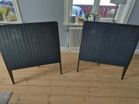
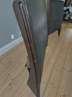
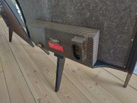
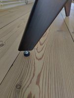
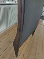
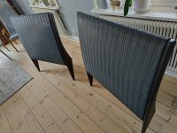
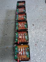
Some photos on the new refurbished with dark handcrafted spiderlegs.
Attachments
-
 IMG_20230205_142230.jpg218.6 KB · Views: 153
 -
 IMG_20230205_142237.jpg76.6 KB · Views: 144
 -
 IMG_20230205_142246.jpg262.3 KB · Views: 142
 -
 IMG_20230205_142329.jpg60.8 KB · Views: 147
 -
 IMG_20230205_142351.jpg72.6 KB · Views: 133
 -
 IMG_20230205_142409.jpg54.4 KB · Views: 153
 -
 IMG_20230205_142424.jpg288.5 KB · Views: 144


I like that you added a fuse to the power supplies.
Sheldon
Sheldon
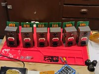
Here is a set of audio transformers restored with new resistors and upgraded to handle more than 15W power as later standard. Those Erie resistors getting high resistance values. fore example a 180K resistor is measures over 220K and I decided to replace them all. Also the weak banana jacks where replaced with some high quality German manufactured ones (no need for drilling). Protection units for the treble panels will start clipping over 2,2KVolt. Original Erine caps used when possible.
Attachments
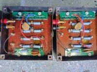
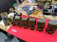
The spacing between your diodes and the mounting screws on your clamp boards is pretty small, you might have arcing from the diode legs to that grounded mounting screw. You might want to conformally coat the board or switch to plastic fasteners (not sure plastic sheet metal screws exist though).
IPC-2221 covers spacing for high voltage circuits if you are interested: https://resources.altium.com/p/using-an-ipc-2221-calculator-for-high-voltage-design
Sheldon
IPC-2221 covers spacing for high voltage circuits if you are interested: https://resources.altium.com/p/using-an-ipc-2221-calculator-for-high-voltage-design
Sheldon
Yes you are right. Good advice. I will cost the boards with spray plastic like with the EHT-boards.
Are those 4 kV ceramic capacitors any good for audio by todays standards? Is there any foil capacitor as a potential replacement? Should it be 4 kV at all?
I am skeptical that the power supply caps would make any difference due to the long time constant for charging the panels.
Maybe leakage is involved, lowering the HV?
The caps only handle voltage charge, so I dont think it matters.Are those 4 kV ceramic capacitors any good for audio by todays standards? Is there any foil capacitor as a potential replacement? Should it be 4 kV at all?
I mean the 560 pF 4 kV ceramic capacitors in the crossover.The caps only handle voltage charge, so I dont think it matters.
Applying coating on both sides is bad. It is counter productive and gives higher distortion.
Charging both sides is not a problem at all, it is the two forces working against each other that is the problem.
Which two forces did you mean? The audio signal's forces are in phase.two forces working against each other that is the problem
With coating on both sides of the Mylar the force is weaker than when applied only to one side. So it looks like they work against each other or at least have interference that does not help. Why, I don't know, but it surely does.
And most important, distortion levels are higher, which also might indicate the two coated sides having some interference.
And most important, distortion levels are higher, which also might indicate the two coated sides having some interference.
- Home
- Loudspeakers
- Planars & Exotics
- Yet another ESL57 rebuild