What is your max k2 and k3 target? What would you be satisfied with?
//
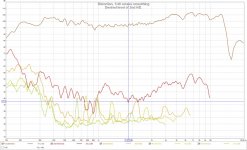
I don't think that -60 dBr for the 2nd HD
and -70 dBr for the higher orders are unreasonable goals.
But want I really want are "smooth" distortion levels without any humps.
Attachments

Thats what I aim at too - at say 90 dB at listening position. Louder and the ear will distort more 😉
Then we shall start measuring IM or some other more challenging test pattern.
//
Then we shall start measuring IM or some other more challenging test pattern.
//
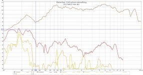
Next try is a 6x2 mm pocket with 6 mm aluminium stripes.
But that was also a lost cause; worse LF, worse HF - a bumpier SPL than ever.

When comparing with the old 6,5x1,6 with 4,5 aluminium,

the 2 mm wide pocket is not the way to go.
So I just have to try to make a better 6,5x1,5 membrane and work to get the LF and HF 2nd harmonic distortion down a bit.
But that was also a lost cause; worse LF, worse HF - a bumpier SPL than ever.
When comparing with the old 6,5x1,6 with 4,5 aluminium,
the 2 mm wide pocket is not the way to go.
So I just have to try to make a better 6,5x1,5 membrane and work to get the LF and HF 2nd harmonic distortion down a bit.
Attachments
Some more DC tests shows that it is only the outermost pockets that visible moves even at a high current for the "all alu" membrane (6x2 mm, alu 6 mm).
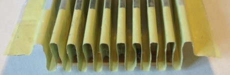
Looking at the membrane it is obvious that it is only the outermost pockets that have bare mylar (half a pocket after/before the initial/ending horizontal section) and that is where the large signal movement is.
This is the end of a 10x2 membrane with "al alu":

For high current that is. The innermost pockets are of course also moving, but they have a stiffer suspension; only the folds'.
So it is then not a surprise that a "all alu" membrane have the above response curve. The outermost pockets have a totally different compliance.
Looking at the membrane it is obvious that it is only the outermost pockets that have bare mylar (half a pocket after/before the initial/ending horizontal section) and that is where the large signal movement is.
This is the end of a 10x2 membrane with "al alu":
For high current that is. The innermost pockets are of course also moving, but they have a stiffer suspension; only the folds'.
So it is then not a surprise that a "all alu" membrane have the above response curve. The outermost pockets have a totally different compliance.
Attachments
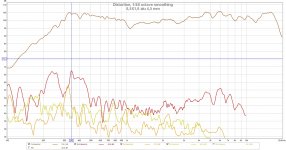
On a 6,5 x 1,6 mm with 4,5 alu in the pockets, the large signal DC test shows other things to consider.
Here the visible movements seems arbitrary. More like the last couple of video some posts ago.
Here is 0 to 10 volts and then down to 0 again applied and then the reversed polarity about 20 seconds in:
AMT DC ramp.
So what is it that we see?
I reckon that every third or fourth pocket or so simply doesn't have any compliance left; it has been consumed by the neighboring pockets and there isn't enough force to claim it.
Also, as the making of the membrane is not that exact, some pockets haven't got their aluminium strips "face to face" and the result is a twist of the pocket instead of a clean collapse/expansion.
In order to mitigate these one could have more free mylar on each side of the aluminium strip, but that will also make the distortion level higher as posted above. The mylar makes too much noise!
But why not try a minor change from 4,5 to 4,0 aluminium.
Another thing to do is to try to make the aluminium strips facing each other in the pockets, so a more carefully designed folding tool is the remedy here. Or at the least try to revise the existing. Also the membrane can be altered a little.
On a 6,5 x 1,6 mm with 4,5 alu in the pockets, the large signal DC test shows other things to consider.
Here the visible movements seems arbitrary. More like the last couple of video some posts ago.
Here is 0 to 10 volts and then down to 0 again applied and then the reversed polarity about 20 seconds in:
AMT DC ramp.
So what is it that we see?
I reckon that every third or fourth pocket or so simply doesn't have any compliance left; it has been consumed by the neighboring pockets and there isn't enough force to claim it.
Also, as the making of the membrane is not that exact, some pockets haven't got their aluminium strips "face to face" and the result is a twist of the pocket instead of a clean collapse/expansion.
In order to mitigate these one could have more free mylar on each side of the aluminium strip, but that will also make the distortion level higher as posted above. The mylar makes too much noise!
But why not try a minor change from 4,5 to 4,0 aluminium.
Another thing to do is to try to make the aluminium strips facing each other in the pockets, so a more carefully designed folding tool is the remedy here. Or at the least try to revise the existing. Also the membrane can be altered a little.
Very good work and observations! :respect:
Seems that, once again, devil's in details 😀
It looks to me that if you want flater fr and less distorsion more precise jig is in order.
What do you think if bend of every pleat is made with more curvature will that have any effect on fr?
Have you thought to try paper for membane?
Keep good work 🙂
Thanks.Very good work and observations! :respect:
Seems that, once again, devil's in details 😀
Keep good work 🙂
Yes, that's my current working assumption.It looks to me that if you want flater fr and less distorsion more precise jig is in order.
I don't think so. Think of the bends as rigid beams. I don't think other shapes will make them softer. If they do, then it will be hard to keep the membrane's structure. So I think that the needed compliance need to come from the bare mylar in the folds. Too much will make noise though.What do you think if bend of every pleat is made with more curvature will that have any effect on fr?
It is also hard to accomplish it.
I did, some 20 years ago with my Tagliatelle clone. That was noisy.Have you thought to try paper for membane?
For sure, there could be other suitable carriers and paper might be one of them, but working with the 74 film is very convenient.
Great idea!maybe kapton? looks like almost every company uses kapton except the original AMT 🙂
Do you have a link on where to get thin Kapton, preferably as tape?
It'll have to sub mil thick, 12" wide and 15" long. Could be on a roll of course.
That's 0,02 mm thick, 300 mm wide and 380 mm long.
I think it'll need to be thermosetting as well, so that the folds will be folds through all the membrane's height.
Here's one, the PIT0.5S-UT-510.
As expensive as the 74 film, about 400 Euros for a roll.
With VAT and delivery and payment charge a roll amounts to $633 though.
I can not tell how it will keep the folds, perhaps a retainers every 100 mm or so are needed.
This looks promising though:
"As a base material, polyimide is extremely versatile as it can be die-cut, punched and thermoformed with or without adhesive."
Last edited:
Noooooo on eBay als wide als 300mm verry verry Cheap to since its used so often for 3d printers. Al are tapes so eat your heart out 🙂
Yes, I went ebaying as well. Didn't find that thin though.Noooooo on eBay als wide als 300mm verry verry Cheap to since its used so often for 3d printers. Al are tapes so eat your heart out 🙂
Do you have a link?
300mm Polyimide Kapton Tape High Temperature Heat Resistant Silicone Adhesive | eBay
easy as typing in kapton tape 300mm
there is a thinner version i believe in 250mm but this is one mill right on the money what you wanted.
easy as typing in kapton tape 300mm
there is a thinner version i believe in 250mm but this is one mill right on the money what you wanted.
Last edited:
"With regard to the Kapton film, the thinnest grade we stock is 50HN (12.7mic) and it is available from 610mm wide. Our price for a 610mm x 5m roll would be £81.42 per linear metre/£407.10 per roll, carriage charges, tax and bank transfer charges will also be applicable."
some how the thinner the more money its worth
, by the way thermo forming kapton ,you might run into some heat problesm since it can stand 280 🙂 your oven wont go there 🙂
some how the thinner the more money its worth
, by the way thermo forming kapton ,you might run into some heat problesm since it can stand 280 🙂 your oven wont go there 🙂
Last edited:
300mm Polyimide Kapton Tape High Temperature Heat Resistant Silicone Adhesive | eBay
easy as typing in kapton tape 300mm
Great! Thanks. For that price it is certainly worth a try.
My search parameters where Kapton tape thin

Some data:
33m Long Reel, 1 Mil thickness - equivalent to 0.001 Inch.
High Temperature Kapton Tape - Heat Resistant to around 260°C.
Silicone Adhesive Backed - Suitable for fixing, masking and sealing in high temperature and voltage applications such as soldering.
i might get a roll as well, it seems very usable material for allot of things like flex PCB's and so on. its easy to get some copper tape and ad it and you got flex pcb. adding aluminium tape gives you a nice etchable membrane for all sorts of speaker projects 🙂
oh since it has adhesive that is heat resistant. just plain aluminium or copper foil is enough, does not even has to be tape 🙂
one last thing, for you connection to the menbrame. i googled around and any Liquid thin for cold tinning should be able to thin the end of the foil so you can make a normal solder connection. did not try this yet but the guys from MG chemical told me it should work.
i think this is what they do in the PRO scene, you noticed the verry shiny etched kapton laminates? i bet its tin. it also acts as barier so it wont decay, and gets brittle
i am at the moment in the progress of making a jig for membranes as well 🙂 sooo many pleates 🙁 its allot of work i must say. especially when it has to be accurate
Last edited:
But for the AMTs you still use the 74 film?I used PVDC or saran for my planars.
It is soft and silent .Used for wrapping chease .
Bernt
- Status
- Not open for further replies.
- Home
- Loudspeakers
- Planars & Exotics
- Yet another DIY AMT