Had some hifi friends over.
We only listened to Mk I and they where all awed by the clarity and fast response of the system over all frequencies.
The treble level some thought were a little tiring in the long run, especially at the high volume levels we were playing at.
To let the frequency response start to fall off from 1000 Hz seemed as a generally good idea; not to strive for a flat frequency response curve that is.
I am want on the other hand all details to be heard; but then I don't listen for hours and certainly not at the levels we were playing. Or perhaps my own hearing is impaired. Anyway, the frequency curve is easily fixed with the DSP.
Even if the didn't listen to Mk II we had many discussions about the construction and the measurement I did just prior to the meeting.
First we did a correlation of my own built measurng microphono (WM61) with a ECM8000.
I learnt that having a looong boom is essential.
It could be worth while to let the wave guide start between the pole pieces in the motor.
What I have now is just a air pressure stopper to avoid leakage that way.
The CD wave guide doesn't have to be that big, perhaps matching the bass elements width is enough.
That way the AMT would also be more integrated into the baffle.
(Maybe the 900 Hz distortion comes from the sloppy floppy Q&D wave guide.)
Could the top at 10 kHz be lowered? Even if I can easily PEQ that in the DSP, it has to be corrected if the AMT:s ever are to be driven passively.
Here it is solely the membrane that need some redesigning. Perhaps make a small test AMT, that would mean smaller membranes as well, were only this is investigated with a short loop between design and measurements.
The overall dimensions for the Mk II are the same as for Mk I.
That is a 320 x 60 mm opening for the sound generating part of the membrane with pole pieces that are 5 mm wide and 5 mm apart.
Mk II has twice as many magnetes and FEMM:ed pole pieces that results in double magnetic flux.
The Mk II membrane is in one piece instead of two glued together and the return leads are outside the magnetic field. Total height of the membrane is 350 mm.
The width of Mk II aluminium foil is 5,5 mm wide instead of 5 mm.
When it comes to the membrane I have to have several pieces of the 74 film as it is only 160 mm wide. To be able to cover the whole width 350 mm I'm using two sheets of 160 mm and two 30 mm. Two 160 mm overlaps 10 mm in the middle and the two 30 mm overlaps them at the bottom and top where the return leads are. A 350 mm wide tape will cost $325. Cost per AMT will only be $2 as the tape roll is 66 m and it will hopefully take 400 mm of the roll.
I reckon that the wider tape is a must though in order to better compliance.
Tests last night revealed that I was too optimistic when it comes to the membrane frame, it is not enough to rely on the small adhesion forces the impure brass rods have to the magnetic structure.
I must put some silicone rubber between the rods and the magnetes as well.
Still struggling with vibrations from the frame.
Silicone rubber between the frame and magnets mitigates the vibrations a bit, but it is time to think outside the box.
So what is causing the frame vibrations?
There are forces acting upon the frame due to that the initial aluminium foil leads are glued to the frame.
Then there is then of course aluminium foil at the first free fold.
The solution is of course obvious once the problem has been formulated; remove the aluminium foil from that part of the membrane and thus start the circuit a couple of folds into the membrane!
The force will not then act directly on the frame. As a bonus the compliance will be higher.
Also, the first aluminium foil leads will then be in the somewhat more linear field.
I will still go for brass as membrane frame but perhaps thinner rods than the 2,5 mm I got now.
I still need to glued the frame to the magnets with the silicone rubber.
The top and bottom of the frame will be nylon spacers/screws but they will be mounted after that the membrane has been inserted.
I have also made some sweeps without baffle, flat baffle, smaller wave guide and larger wave guide but the wave guide size Mk I has performs the best.
I will probably have to make new ones though as the Mk II mounting differs a bit.
What about some air transparent cloth in front and back of the membrane?
This will give less ratteling, and a air resistance lowering the Q value.
Some electrostatic speakers has a mesh very close to the membrane (4mm, Quad ESL 63)
This will give less ratteling, and a air resistance lowering the Q value.
Some electrostatic speakers has a mesh very close to the membrane (4mm, Quad ESL 63)
Great idea but I already tried that on Mk I. Didn't help.
In fact, it created more noise.
There's ideally only 1 mm between the membrane and the pole pieces.
In fact, it created more noise.
There's ideally only 1 mm between the membrane and the pole pieces.
What if you used magnetic paint for the brass frame.
The frame would stick to the magnets.
You might "divide" the membrame, gluing a trace of silicone 1/3 up across the membrane.
Bernt
The frame would stick to the magnets.
You might "divide" the membrame, gluing a trace of silicone 1/3 up across the membrane.
Bernt
Thanks for the idea, båndsei. But the brass alloy has a little iron impurity, so it adheres to the magnets already.What if you used magnetic paint for the brass frame.
The frame would stick to the magnets.
You might "divide" the membrame, gluing a trace of silicone 1/3 up across the membrane.
Bernt
But obviously not enough. I doubt that magnetic paint will improve the adherence to that extent that it will be enough to avoid vibrations.
I have 1,5 mm x 4 mm instead of the 2,5 mm x 7 mm in order to make place for a first suspension pocket.
(I will try to get hold of 1 mm x 6 mm. Maybe a carbon fiber stick has the desired stiffness)
So with the thinner brass frame I will still get 60 mm of effective membrane width; the first pocket wall that as aluminium foil in the voice coil circuit will be the third. (Yes, there will be two Empty Pockets, one on each side of the membrane)
There will still be aluminium strips in the first two pocket walls though, but only as guides to the brass frame.
Got a clue on the dips a highs around 10 kHz and up.
It could be reflections between the pole piece and the bottom of the pockets.
The distance varies between 8 to 7 mm corresponds and the corresponding wavelength is a frequency range of 43 to 49 kHz, that is about 10 to 12 kHz if the 1/4 wave lengths are considered.
So perhaps some cloth on the part of the pole pieces that is toward the membrane and then cut out for the space between the pole pieces for the forward sound wave.
On the back, the cloth can remain uncut as the back isn't loaded with any wave guide.
When it comes to the compliance I don't think that the actual folds contributes that much. I mean, even if the fold can be contracted to a certain amount, it is very hard for it to be expanded beyond its shape when at rest.
Even if I get some compliance from the folds that compliance is then asymmetrical through the fold side's movement.
Did some DC tests (finally) and I only saw movement on the suspension part that has no aluminium according to the previous post.
So perhaps I have too much aluminium in the pleats thus not meaning any free movements of the pleats.
Reducing the width of the aluminium from 5,5 mm to 4,5 mm will up the resistance to 8 ohms, so that will be my first try.
I then expect the LF response be better and also lower distortion levels.
I have 14 um BBQ aluminium foil as well, with that I may go to 3 mm (8,5 ohm).
No paper backing though, so it might prove hard to make a membrane of it; the cutting machine ripped the aluminium apart the last time I tried.
Making the bottom of the pocket V-shaped might mitigate this as the quality factor (Q) then should be lower.It could be reflections between the pole piece and the bottom of the pockets.
Membrane version 4
Had a discussion with onni about what contributes to the compliance and it lead to trying a narrower aluminium foil, 4,5 mm instead of 5,5 mm.
The resistance is 8,5 ohm, so it is still acceptable.
Here´s a comparision with v3 that had 5,5 mm:

SPL is 111 dB/1m @ 9 kHz.
I now fasten the membrane on the brass rods with VHB but now only on the inside of the rod. It really holds.
Still some issues with vibrations in the low end that leads to high distortion levels though. But I´ll deal with that later.
And for those of you who really feel an urge to analyse...
Version 4 only, raw:

1/24 octave smoothing:

1/18 octave smoothing:

1/12 octave smoothing:

1/6 octave smoothing:

1/3 octave smoothing:

Had a discussion with onni about what contributes to the compliance and it lead to trying a narrower aluminium foil, 4,5 mm instead of 5,5 mm.
The resistance is 8,5 ohm, so it is still acceptable.
Here´s a comparision with v3 that had 5,5 mm:
SPL is 111 dB/1m @ 9 kHz.
I now fasten the membrane on the brass rods with VHB but now only on the inside of the rod. It really holds.
Still some issues with vibrations in the low end that leads to high distortion levels though. But I´ll deal with that later.
And for those of you who really feel an urge to analyse...
Version 4 only, raw:
1/24 octave smoothing:
1/18 octave smoothing:
1/12 octave smoothing:
1/6 octave smoothing:
1/3 octave smoothing:
A reflection
So what is causing the raise in frequency response around 9 kHz and 18 kHz?
I have earlier mumbled about the pockets being Helmholtz resonators given the depth of the pockets.
This is of course not the case even though the pocket depth has something to do with it.
The backward sound wave is simply reflected at the back pole pieces and, being 180 degrees from the beginning, superimposed with the forward sound wave.
Likewise, the forward sound wave is reflected on the front pole pieces back at the back pole pieces and then also superimposed on the forward sound wave.
At double the frequency it happens again and in between and above there are cancellation effects instead.
The sound wave isn't generated at a discrete point in the pocket, so the "Q" of the frequency response of these effects aren't that high.
The 9 kHz raise is of course easily EQ:ed and I don't bother about what is going on above 18 kHz anyway.
But are the effects of the reflected sound waves coming from the same source and delayed a fraction of a millisecond*, audible?
*That is, the time it takes for the sound to travel 10 to 20 mm.
I concur with your thoughts, those pesky plate reflextions muck up an otherwise nice image. I say that because these very short reflections could only have an issue with imaging at the last octave dot five or so. Don't believe there is that much detail up that high anyway... it's mostly transient and ether.
I wonder how the plates would model if a 45 degree chamfer was appplied to the inner edge?
My push pull planars have similar issue. In that case the magnets are where your plates are. 6mm square, 126mm long x 4 pair
I wonder how the plates would model if a 45 degree chamfer was appplied to the inner edge?
My push pull planars have similar issue. In that case the magnets are where your plates are. 6mm square, 126mm long x 4 pair
Yes, it all makes sense.I concur with your thoughts, those pesky plate reflextions muck up an otherwise nice image. I say that because these very short reflections could only have an issue with imaging at the last octave dot five or so. Don't believe there is that much detail up that high anyway... it's mostly transient and ether.
Yes, some diffraction could be good. No use in trying to dampen this.I wonder how the plates would model if a 45 degree chamfer was appplied to the inner edge?
Hard for me to modify the pole pieces in the motors I already have built though.
I could try to make the gap narrower and use a thinner membrane and thus push the frequency up a bit.
So something V-shaped 2 mm thick in the middle and 5 mm wide on each back pole piece.
I guess you can't dull the magnets, have you thought of any other remedy?My push pull planars have similar issue. In that case the magnets are where your plates are. 6mm square, 126mm long x 4 pair.
Last edited:
Further discussions with onni lead me to test a dampening box, I also used some cotton thread in order to tie the brass rods to the magnets.
They centered the membrane as well reduced some LF noises.

Then I measured at 10, 20 and 30 cm distance. Level at loudspeaker's terminals was 3 V RMS. Smoothing 1/24 octave, sampled at 88,2 kHz and frequency sweep from 125 Hz to 20000 Hz.
Got the same highs at 8,5 and 17 kHz.
Below 3 kHz does the distortion level vary with the distance of the microphone and I guess that the room has something to do with the response below 1 kHz.
10, 20 and 30 cm SPL and phase:

Second harmonic distortion:

Third harmonic distortion:

Directivety at 0, 15 and 30 degrees:

Then I put on a top and bottom on the box (blue), still not air tight though (THD shown):

Did a comparision with a simple baffle (red), 75 cm wide in total (THD shown):

The same with 3rd harmonic distortion shown:

Now these measurements are not done at one meter let alone at the sweet spot and no wave guide either, but I think that it is absolutely worth investigating having a sealed dampening box behind the AMT.
Also, of couse, it is good to get a good fastening of the membrane frame; the thread also help in straighten the brass rod as it tends to bulge inwards.
They centered the membrane as well reduced some LF noises.
Then I measured at 10, 20 and 30 cm distance. Level at loudspeaker's terminals was 3 V RMS. Smoothing 1/24 octave, sampled at 88,2 kHz and frequency sweep from 125 Hz to 20000 Hz.
Got the same highs at 8,5 and 17 kHz.
Below 3 kHz does the distortion level vary with the distance of the microphone and I guess that the room has something to do with the response below 1 kHz.
10, 20 and 30 cm SPL and phase:
Second harmonic distortion:
Third harmonic distortion:
Directivety at 0, 15 and 30 degrees:
Then I put on a top and bottom on the box (blue), still not air tight though (THD shown):
Did a comparision with a simple baffle (red), 75 cm wide in total (THD shown):
The same with 3rd harmonic distortion shown:
Now these measurements are not done at one meter let alone at the sweet spot and no wave guide either, but I think that it is absolutely worth investigating having a sealed dampening box behind the AMT.
Also, of couse, it is good to get a good fastening of the membrane frame; the thread also help in straighten the brass rod as it tends to bulge inwards.
damned dude, you are getting there. every few months later you go lower. i admire your dedication!! , looking awesome and wtf 110 db eff..... jesus 1 watt is enough to get you hearing damage 🙂 about the reflections, there is ofcourse not much room to dampen them i guess 🙁 ?, and rounded bars would make a difrerence but if will affect the field as well.. hmm what to.
Yes for sure, it gets better and better.
One of these days I will actually listen to music through them.
One of these days I will actually listen to music through them.
First membrane with the 360 mm wide tape (the paper under it is of A3 size):
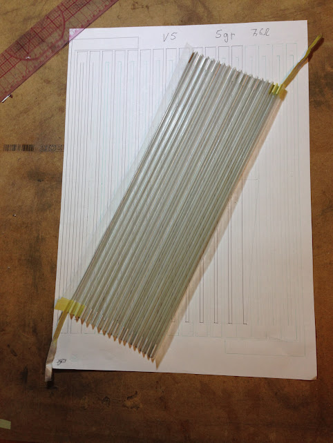
Now isn't that a beauty!
I expect an even compliance along the folds and for sure higher compliance where seams were. So hopefully I'll get better LF response and also lower distortion levels.
Based on a suggestion by onne, I removed one pocket so now there's an equal amount pockets on the front and on the back of the membrane.
As onni pointed out, there's otherwise a residual force that modulates the membrane in the paper's plane.
Hopefully the mounting of the membrane into the motor will now be less critical.
I will also dull the edges of the pole pieces a little, both front and back as well as the inside and outside.
Perhaps the 9 kHz reflection will be lower having less surface to bounce at.
Less diffraction and also more space for the front wave. (Yes, higher LF response and overall lower distortion).
I will only dull half the pole pieces at first, measuring at 10 cm will be close enough to be able to measure the difference.
Hi Wrinex, I hope that you have noted that I now have great use of the VHB tape I bought a couple of months ago.
- Status
- Not open for further replies.
- Home
- Loudspeakers
- Planars & Exotics
- Yet another DIY AMT