Oblivion
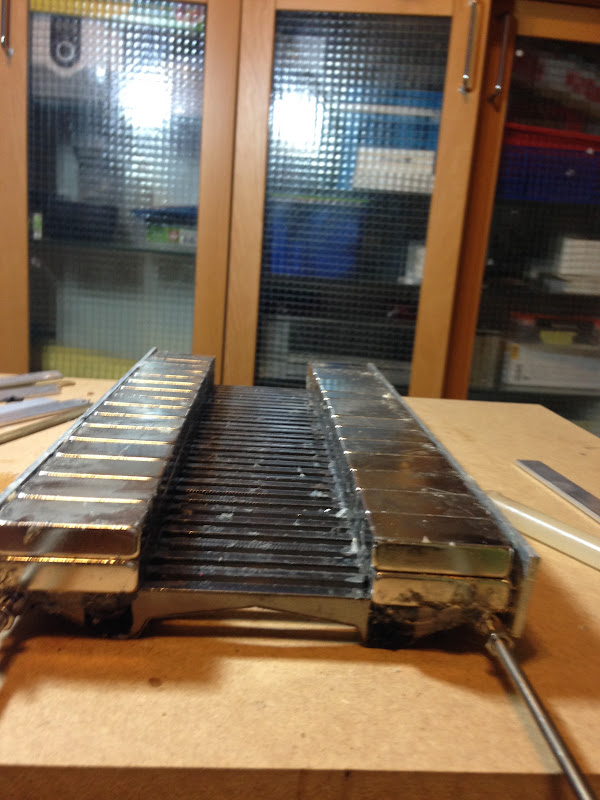
First test of diffracting back pole pieces:
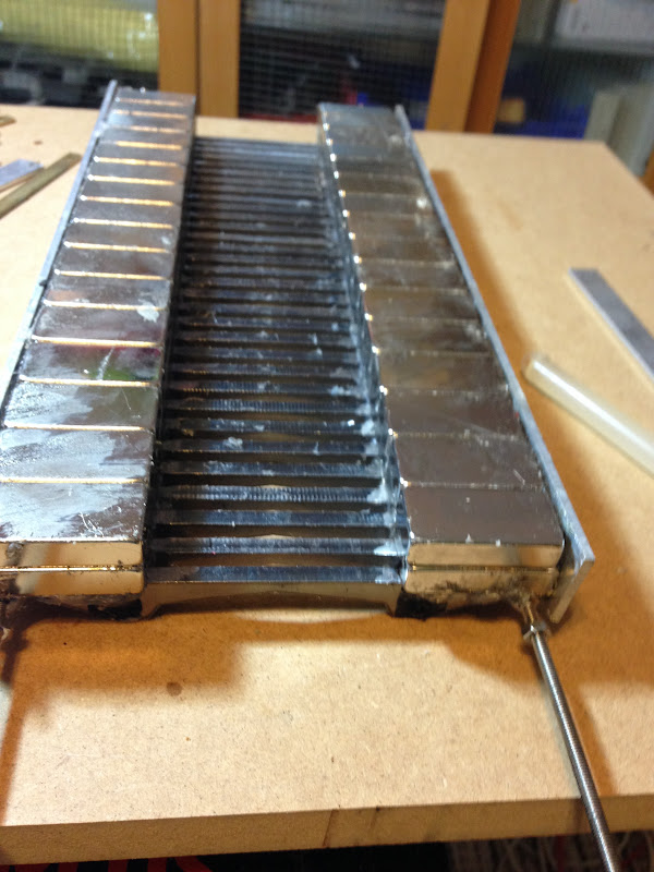
Tests were made on Mk I.
To the left is the original back pole pieces (they are the same as those in front),
in the middle 2x15 mm iron rods that are cut and tilted where the magnet gap will be
and to the right some dampening material I put between the pole pieces.
This is the final setup with; cut and dampened:


Some measurements then. All done at 50 cm with 1 W. Smoothing 1/12.
Original back pole pieces (red) compared to the cut ones (blue):
Nothing much happened, just a shift down for the "hump".
Cut ones (red) vs with some dampening (blue):

Not any significant changes of the hump.
But overall was SPL reduced, so perhaps the reflected wave was reduced.
If so, it was at the cost of higher distortion levels, almost 15 dB for some frequencies.
First test of diffracting back pole pieces:
Tests were made on Mk I.
To the left is the original back pole pieces (they are the same as those in front),
in the middle 2x15 mm iron rods that are cut and tilted where the magnet gap will be
and to the right some dampening material I put between the pole pieces.
This is the final setup with; cut and dampened:
Some measurements then. All done at 50 cm with 1 W. Smoothing 1/12.
Original back pole pieces (red) compared to the cut ones (blue):
Nothing much happened, just a shift down for the "hump".
Cut ones (red) vs with some dampening (blue):
Not any significant changes of the hump.
But overall was SPL reduced, so perhaps the reflected wave was reduced.
If so, it was at the cost of higher distortion levels, almost 15 dB for some frequencies.
What is the pore density (ppi) of the foam dampening used? Dr. Geddes uses 20ppi reticulated foam for his waveguides and 30ppi for enclosure dampening. Both are used as filter foam in HVAC.
I think the PPI is slightly higher, perhaps even the double. Me squeezing it to a third of its original PPI didn't make it better.
The PPI isn´t stated by the vendor (Geko 1100/50).
Still reticulated though.
The PPI isn´t stated by the vendor (Geko 1100/50).
Still reticulated though.
Last edited:
Got some proper HVAC foam with 20 PPI from the local hardware store.
But the correct place is between the membrane and the back pole pieces.
So I must make space for the foam as it is 10 mm thick.
I also have to modify the Mk II motor at some point; the back pole pieces will have to go or at the least be replaced by a thinner pole piece in order to get less reflected area. Perhaps 2 mm instead of 5 mm.
So building a rather complex pole pieces with many small iron pieces lead to this:
(Spent one hour or two at FEMM to get this far)
For sure not linear enough across the gap:
Last edited:
More magnets, more magnets ...
I will try to build this motor, let's call it Mk II B:


Now the magnetic flux density is linear!

I will try to build this motor, let's call it Mk II B:
Now the magnetic flux density is linear!
Last edited:
Now that's a beast of a motor! Funny if you get that 8dB back. 😉
Will this be used with a rear enclosure or dipole with the waveguide on the front?
Will this be used with a rear enclosure or dipole with the waveguide on the front?
http://www.pctmg.nl/uploads/API-Brochure.pdf
I think they are selling is Armco. TELAR 57 are cleaner and more costly
I think they are selling is Armco. TELAR 57 are cleaner and more costly
Last edited:
Finally 🙂snail🙂 got two bare Mk II B ready.It´ll be the double amount of magnets (total of 64) and the same size (N42 40x20x10 mm).
Two layers of magnets and only the front pole pieces permanently (I hope) mounted.
I've also tried to make an initial waveguide throat with glue sticks, couldn't finish it though as the glue gun melted and cut the power.

Not the prettiest things I've made but certainly two of the most lethal 😱.
Now I can start experimenting with both size and shape and number of the back pole pieces.
Also the position of the membrane and HVAC foam in the now 20 mm gap.
But first some simulations...
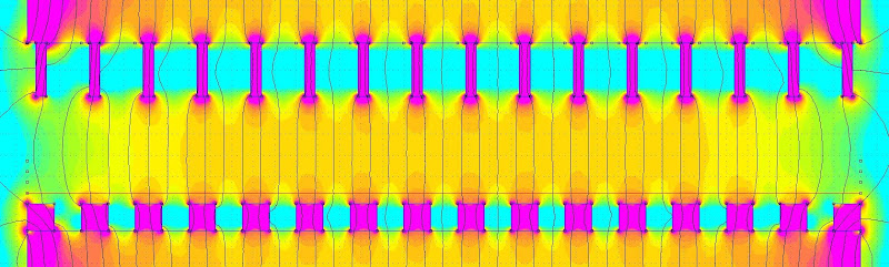
So in order to get relative comparisions one might turn the inside out of the motor, applying a sink/source to get some kind of circuits:
In that case could the Mk II motor with the single layer of magnets look like this:

In that case could the Mk II motor with the single layer of magnets look like this:
Last edited:
So just showing levels between 0,25 and 0,75 T it could be visualized as:

a rather varying flux density will be what the foil's outer rim will get (red line above):

more than, boundary conditions unaccounted for, more than +/- 0,5 T.
Suddenly it is not only the unwanted reflections from the back pole pieces that needs to be reduced...
a rather varying flux density will be what the foil's outer rim will get (red line above):
more than, boundary conditions unaccounted for, more than +/- 0,5 T.
Suddenly it is not only the unwanted reflections from the back pole pieces that needs to be reduced...
Again, please note that for this fake motor, the corresponding real magnetic flux density is probably not even half of what is shown above.
So also the variations are a magnitude less, but should be able to be used for comparative studies.
In this fake, inverted, motor, the foils in the membrane are parallel with the red line so the Lorentz force is making the membrane's fold moving in and out in the paper's plane as the current varies with the applied signal.
It is not so good that this force then is varying along the fold.
Of course, if the fold is stiff enough it doesn't matter, but I suspect that there are modes that results in resonance patterns with resulting distortion as well.
Such modes will appear at frequencies corresponding to from 10 mm to 310 mm with a 10 mm granularity (cc of the pole pieces) plus the half and quarter wave lengths.
(And I guess 1/8 and so on as well but they will be of less amplitude and buried in the overall "noise" anyway.)
Many modes will of course be superimposed (that will be superimposed!) producing even higher dips and highs in the frequency response curve.
So the Mk II design (and Mk I!) was flawed from the beginning.
And of course all other simple bar AMTs out there.
One countermeasure is of course to go the Båndsei way of "Look, no bars", but that causes other problems such as weak and non-linear magnetic flux intensities.
Another way is to have the pole pieces at a not repetitive interval but that will only reduce the superimposed modes, not removing the actual modes.
A third way is to... Sorry, that will be another time. Or, quoting another famous monologue: "II B or not II B".
Last edited:
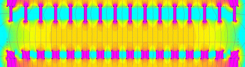
So here's the inverted view of the Mk II B motor:

The magnets are pulled further away to get the 20 mm gap.
Note also that it is only half the motor that is shown.

The magnets are pulled further away to get the 20 mm gap.
Note also that it is only half the motor that is shown.
Simulated:
The foil along the red line above will have these fluctuations:

Not so great.
But what if the membrane were pushed back, that is up in this view, a couple of millimeters?
Great improvement:

I don't know how well this simulated view corresponds to any real conditions, but it is easily verified; just put the membrane to and fro and measure.
The foil along the red line above will have these fluctuations:
Not so great.
But what if the membrane were pushed back, that is up in this view, a couple of millimeters?
Great improvement:
I don't know how well this simulated view corresponds to any real conditions, but it is easily verified; just put the membrane to and fro and measure.
If the foam is pushed back, perhaps with cutouts for the back pole pieces, there will be less dampening and diffraction of the back wave and its reflection on the back pole pieces.
One remedy for the lost diffraction is so make the back pole pieces edges not so blunt:

Simulated:
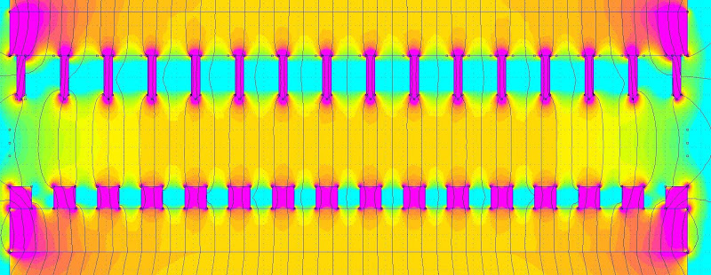
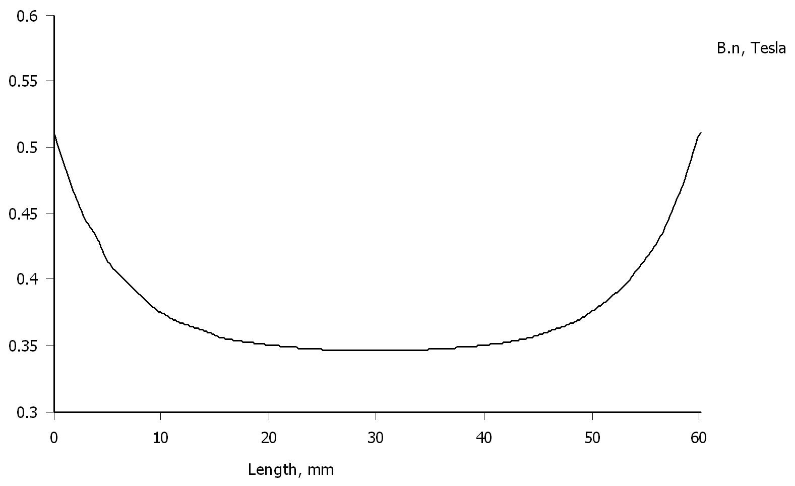
Flux density variation in the center of a membrane in the middle of the gap:

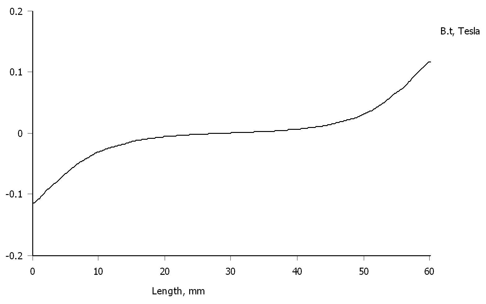
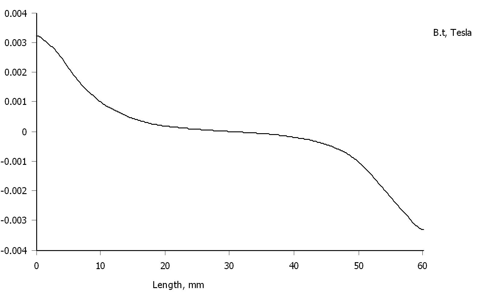
and at the rim:

Now this looks promising.
One remedy for the lost diffraction is so make the back pole pieces edges not so blunt:
Simulated:
Flux density variation in the center of a membrane in the middle of the gap:
and at the rim:
Now this looks promising.
- Status
- Not open for further replies.
- Home
- Loudspeakers
- Planars & Exotics
- Yet another DIY AMT