I´ll fold
First tests with the new folding tool:
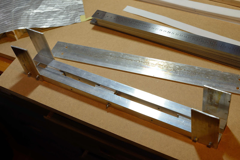
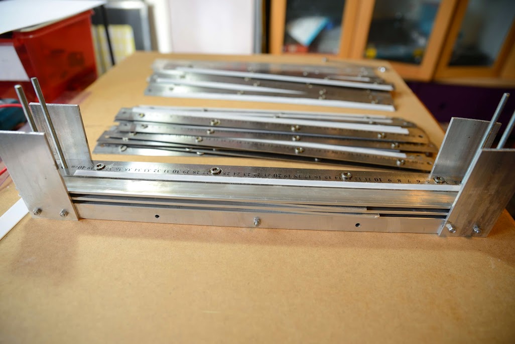
Width is okay, but I might add a couple of båndsei pins. Also, the ruler must have some support:


First 320 mm high membrane:

Not the full width though, but it looks promising:
So I got some work to do on the precision. But considering that this was a sloppy test made with a test membrane, with a little patience even this first version of the tool might be enough.
First tests with the new folding tool:
Width is okay, but I might add a couple of båndsei pins. Also, the ruler must have some support:
First 320 mm high membrane:
Not the full width though, but it looks promising:
So I got some work to do on the precision. But considering that this was a sloppy test made with a test membrane, with a little patience even this first version of the tool might be enough.
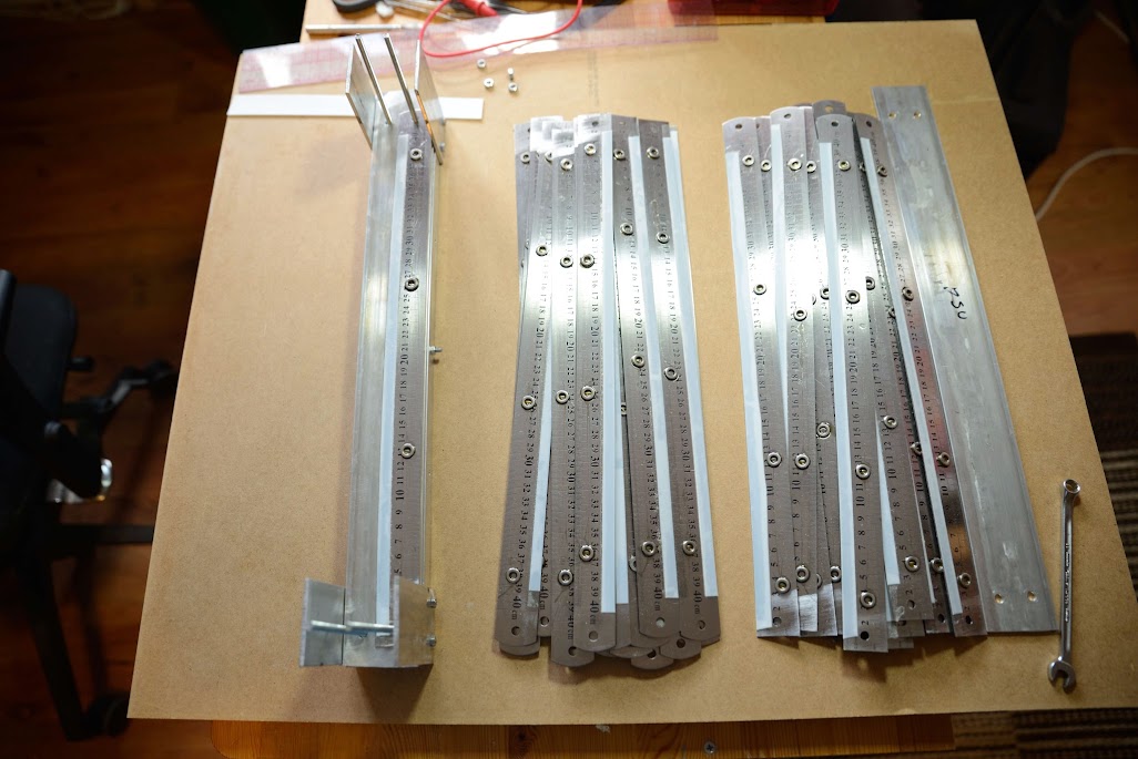
So with the second motor finished as well, it took a little more time than I anticipated as I was impatient and did not let the glue cure when I tried to glue the next magnet, it is time to start with some serious membrane manufactoring.
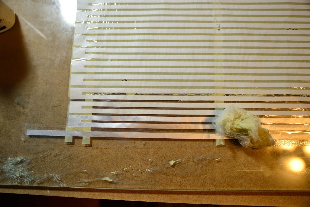
The unfolded membrane is 350 mm high and 330 mm wide and as the Silhouette cutter only takes 300 mm and the foil is even less wide I will have to make two foils:

The two foils must be exactly 2,6 mm apart:
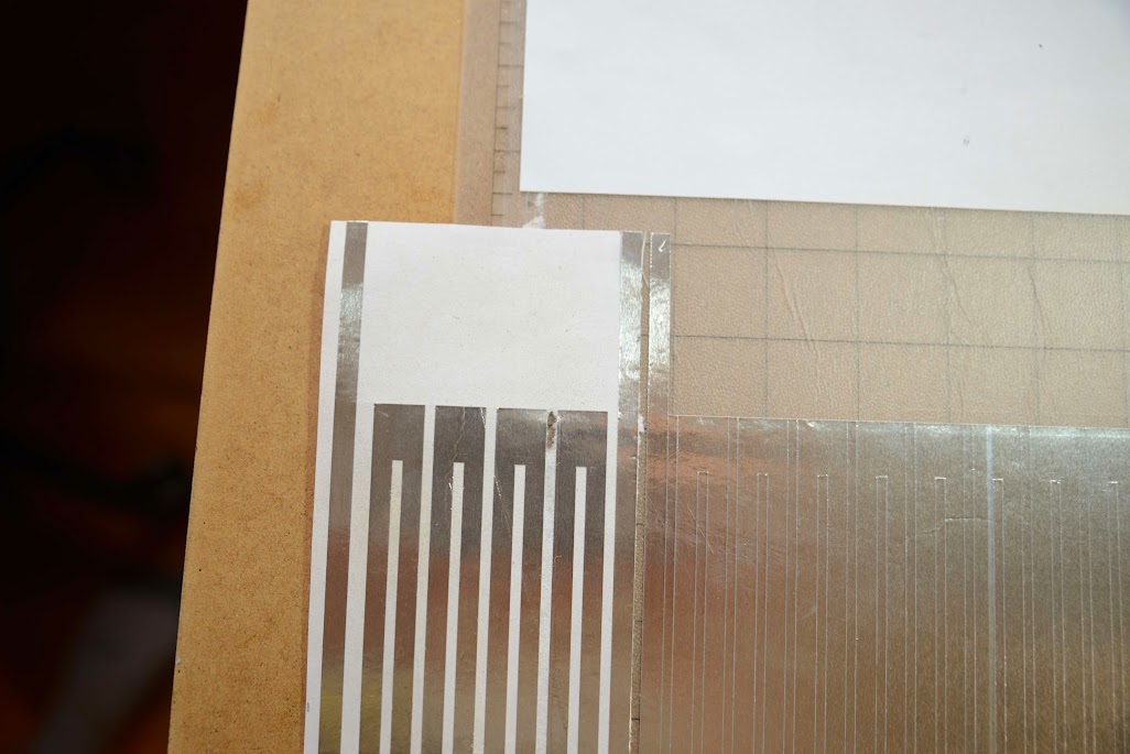
Somehow I will join the electrical leaders in order to make one circuit
The unfolded membrane is 350 mm high and 330 mm wide and as the Silhouette cutter only takes 300 mm and the foil is even less wide I will have to make two foils:
The two foils must be exactly 2,6 mm apart:
Somehow I will join the electrical leaders in order to make one circuit
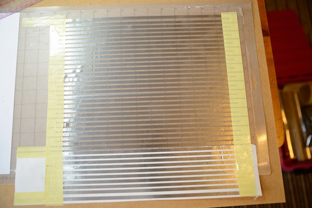
I let the knife cut a little too deep on the large membrane part so that the PressnSeal I have between the cutting mat and the paper I have as a in-between layer got cut as well.
A little more to cleanse, but not a huge problem.
The widest tape I got is 160 mm, so I will have to have put several layers of tape.
I secure the distance between the foil with a narrower tape first at the return parts.
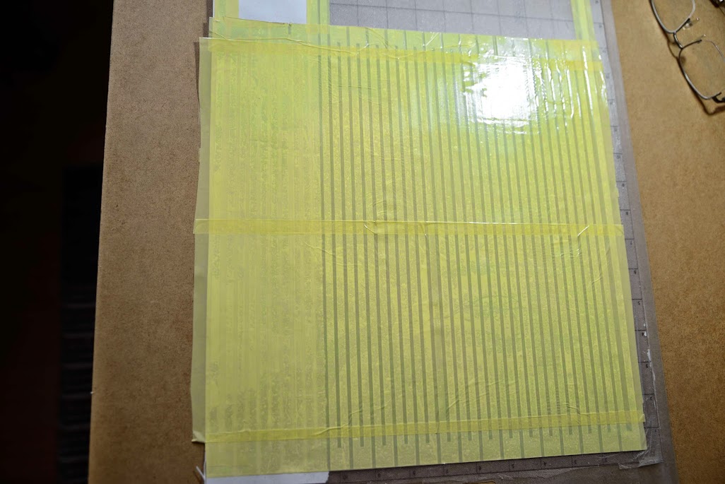
Wasn't all that concentrated so I got some unwanted folds:
A little more to cleanse, but not a huge problem.
The widest tape I got is 160 mm, so I will have to have put several layers of tape.
I secure the distance between the foil with a narrower tape first at the return parts.
Wasn't all that concentrated so I got some unwanted folds:
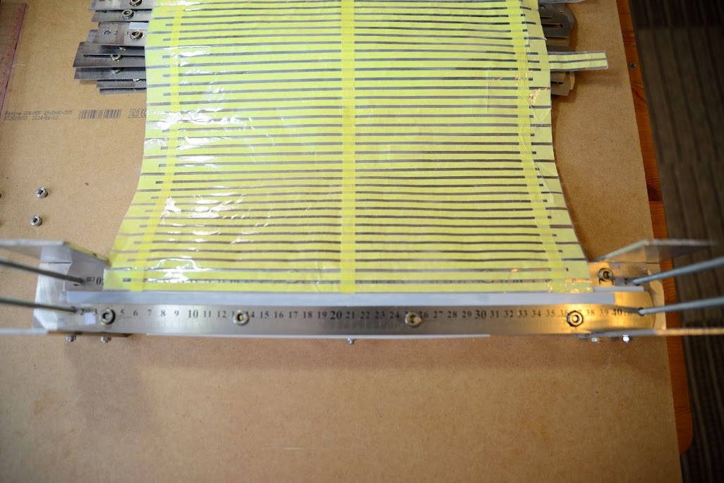
For the wider tape I use the mounting help as usual:
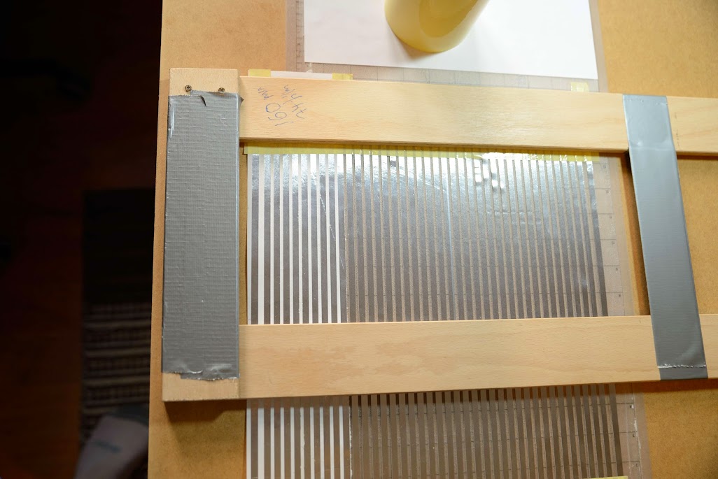

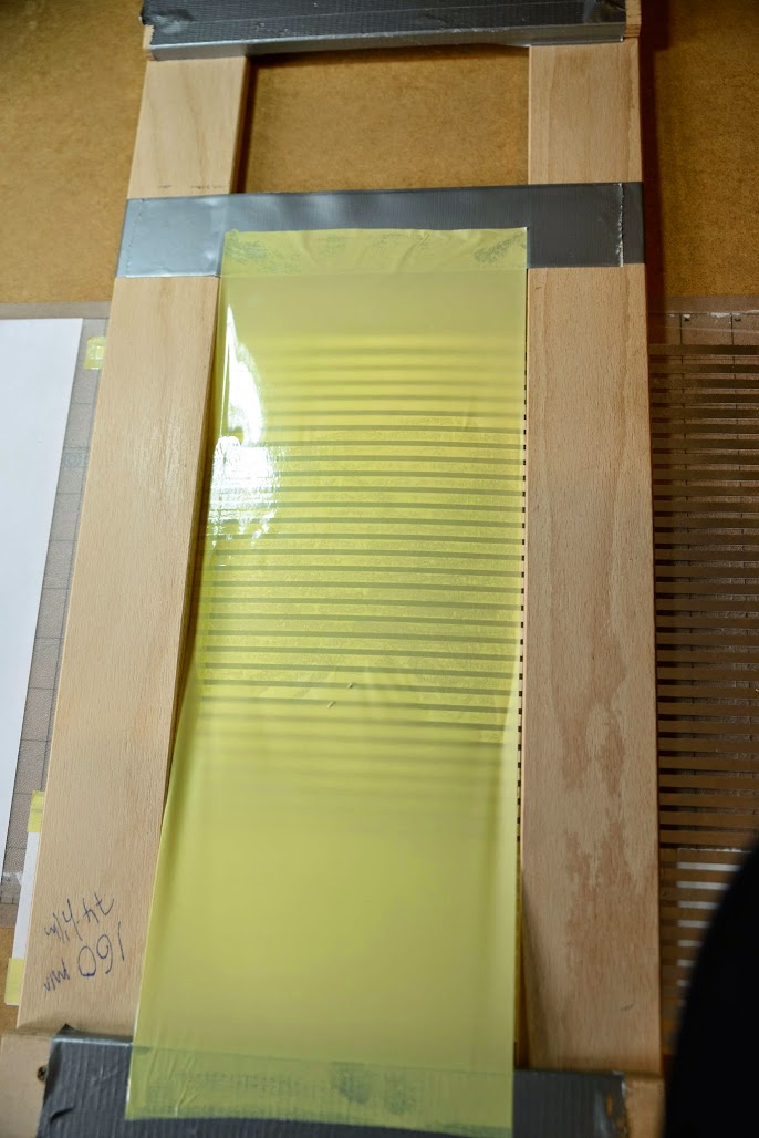


Could have been more careful when applying the tape...
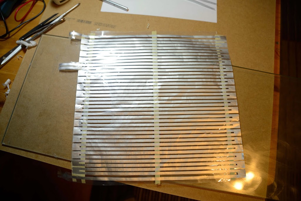
Finally the whole membrane is covered with the 74 film:
It's been a year since I made the last membrane, got some skills to refresh.
I'm satisfied this far though.
Could have been more careful when applying the tape...
Finally the whole membrane is covered with the 74 film:
It's been a year since I made the last membrane, got some skills to refresh.
I'm satisfied this far though.
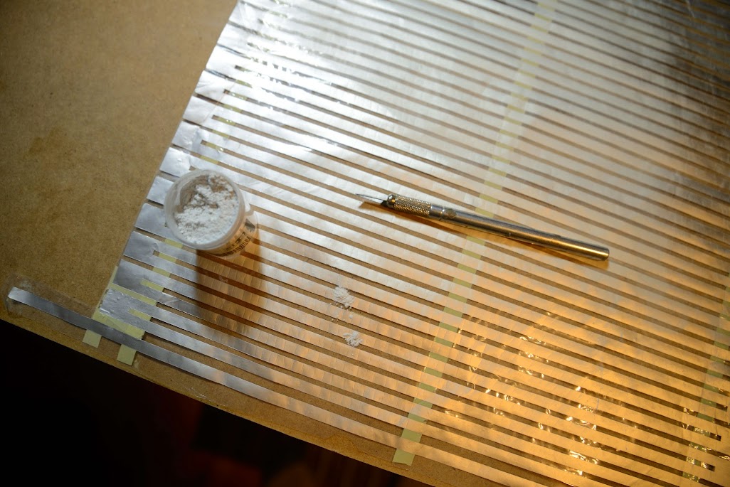
Making the film bond to the aluminium foil better using an old layout tool.
Then it is cleansing time:
BTW, I decided against having aluminium foil between the strips, that is in the pocket.
Some minutes later:
Some powder to bind any glue residues:
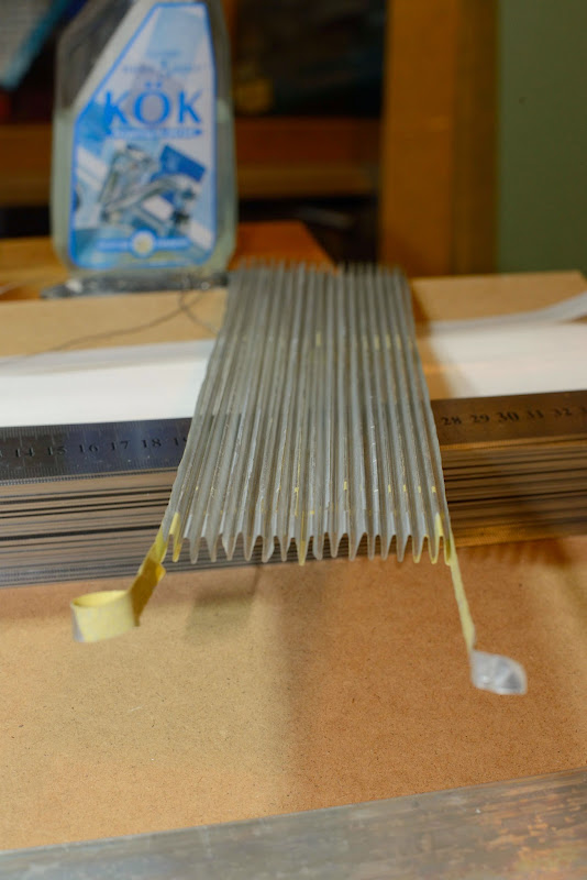
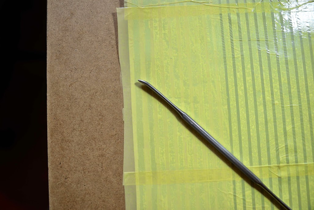
Then it is folding time.
Then it is cleansing time:
BTW, I decided against having aluminium foil between the strips, that is in the pocket.
Some minutes later:
Some powder to bind any glue residues:
Then it is folding time.
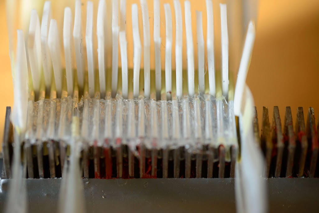
Made a rather complicated folding tool with rulers, PTFE strips and washers:
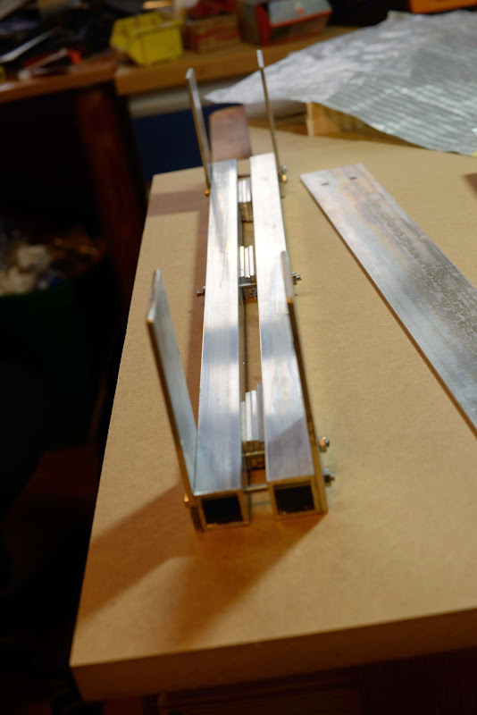
Get set:
Ready:
and fold!
Some minutes later it is time for the oven; 170 degrees Celcius for 25 minutes:
Takes some time to cool down, so I will check the membrane later today.
Stay tuned...
Get set:
Ready:
and fold!
Some minutes later it is time for the oven; 170 degrees Celcius for 25 minutes:
Takes some time to cool down, so I will check the membrane later today.
Stay tuned...
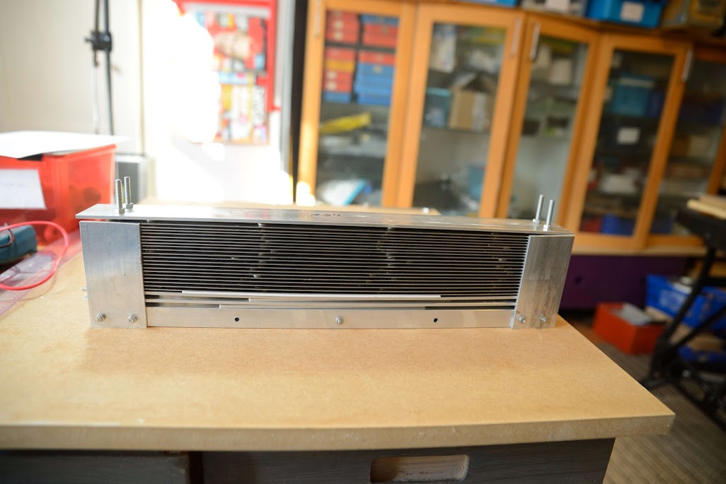
Same old story really as in Mk I, but double the size:
The membrane is released from the mounting tool:
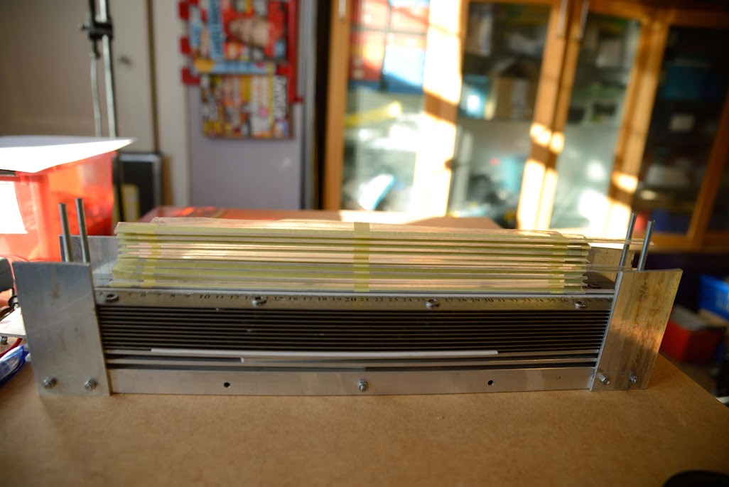
Looking good:
It is a little rough around the edges, but those parts are cut away anyway.
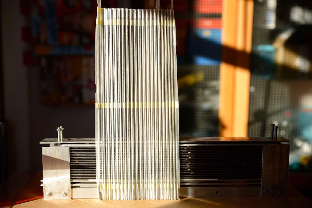
Setting the top with yet another mounting tool, should have two. Now I´ll have to wait until the silicone sealant cures.
The membrane is released from the mounting tool:
Looking good:
It is a little rough around the edges, but those parts are cut away anyway.
Setting the top with yet another mounting tool, should have two. Now I´ll have to wait until the silicone sealant cures.
Oh, man!
Look outside if there are strong lights in the sky around your place ... 😀
Looking very good!
Best of lucks.
M.
Look outside if there are strong lights in the sky around your place ... 😀
Looking very good!
Best of lucks.
M.
I meant perhaps the ET's are looking for you 😀
There may be UFO's out there, hehe.
That kind of quality in a home environement is awesome...I hate that english word but here it is deserved...

I forgot: and totally Off-topic, what do you guys use as passive crossover for the AMT type speakers? Two way...
Cheers,
M.
There may be UFO's out there, hehe.
That kind of quality in a home environement is awesome...I hate that english word but here it is deserved...
I forgot: and totally Off-topic, what do you guys use as passive crossover for the AMT type speakers? Two way...
Cheers,
M.
Yes, with all those Neos I have I can easily pull a UFO down .
I don't know about passive XOs; I have had active XOs for the past 20 years and the last 5 of those I've been digital, doing everything in the DSP in the PC.
In fact, my setup is "Bi DACed", having two channels for the AMT and two channels for the bass.
In my view, the DSP is necessary for the AMTs as they need to be PEQ:ed.
This is how my DSP is currently setup:
Low channels (dipol compensation 6 dB LP from 30 Hz, resulting in +15 dB):
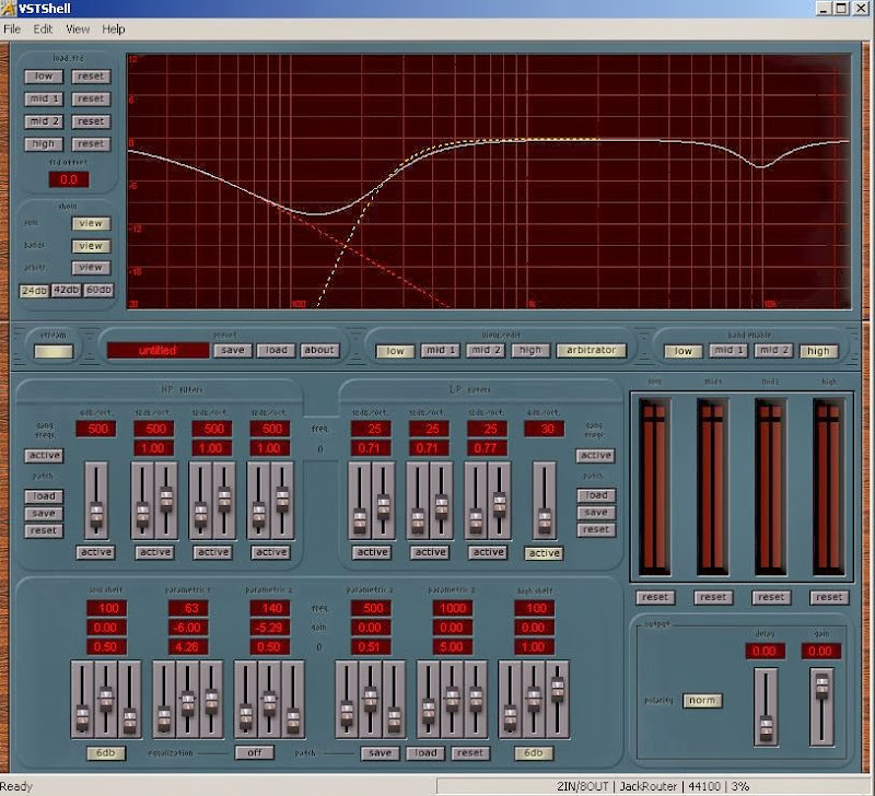
High channels (HP from 250 Hz, some PEQ at 10 kHz):

It includes bass dipole cancellation compensation as well; the output for 20 Hz depicted above is actually +15 dB as the bass amplifiers and speakers result in a higher SPL. At the XO, that is 250 Hz, the SPL for the AMT and the bass are the same.
Also, it could be good to have a step cutoff frequency rolloff for the AMN in the low end; I'm currently using -24 dB.
I don't know about passive XOs; I have had active XOs for the past 20 years and the last 5 of those I've been digital, doing everything in the DSP in the PC.
In fact, my setup is "Bi DACed", having two channels for the AMT and two channels for the bass.
In my view, the DSP is necessary for the AMTs as they need to be PEQ:ed.
This is how my DSP is currently setup:
Low channels (dipol compensation 6 dB LP from 30 Hz, resulting in +15 dB):
High channels (HP from 250 Hz, some PEQ at 10 kHz):
It includes bass dipole cancellation compensation as well; the output for 20 Hz depicted above is actually +15 dB as the bass amplifiers and speakers result in a higher SPL. At the XO, that is 250 Hz, the SPL for the AMT and the bass are the same.
Also, it could be good to have a step cutoff frequency rolloff for the AMN in the low end; I'm currently using -24 dB.
Last edited:
Impressive.
I've been thinking about doing all in one big chassis to avoid ground loops: source--> volume control/active XO-->amps. 😎
But I also want to try something newer and possibly better than the original passive from ESS...
Cheers,
M.
I've been thinking about doing all in one big chassis to avoid ground loops: source--> volume control/active XO-->amps. 😎
But I also want to try something newer and possibly better than the original passive from ESS...
Cheers,
M.
Now I got two Mk II playing, so now I got stereo 😀 --- 😀
Did the first measurements: + 10 dB SPL, considerable lower distorsion and... no noise at the lower frequencies.
Not bad at all for a first go.
Need to work on the slightly higher distortion level at 900 Hz though.
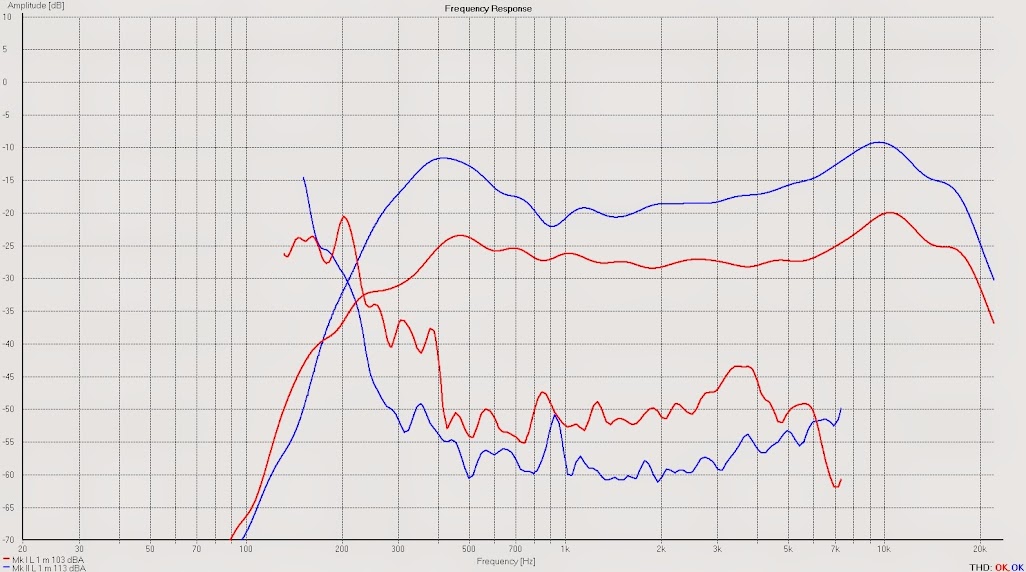
Red is Mk I, blue is Mk II. Sweep from 125 Hz. 1/3 octave smoothing.
Did the first measurements: + 10 dB SPL, considerable lower distorsion and... no noise at the lower frequencies.
Not bad at all for a first go.
Need to work on the slightly higher distortion level at 900 Hz though.
Red is Mk I, blue is Mk II. Sweep from 125 Hz. 1/3 octave smoothing.
Looks really good, congrats 🙂
Below 1% dist above 400 Hz, except for that 900 Hz peak which could be audible. Any idea what causes it (which harmonic is it)?
Below 1% dist above 400 Hz, except for that 900 Hz peak which could be audible. Any idea what causes it (which harmonic is it)?
Please show harmonics between 2 - 5th and use less smoothing. Say no more than 12th octave should do. For critical measures I normally use 24th or 48/oct
REW has a new variable curve where more smoothing is added as frequency increases. Makes for a nice plot and believe is more represenitive of how we hear. 😉
REW has a new variable curve where more smoothing is added as frequency increases. Makes for a nice plot and believe is more represenitive of how we hear. 😉
Looks really good, congrats 🙂
Below 1% dist above 400 Hz, except for that 900 Hz peak which could be audible. Any idea what causes it (which harmonic is it)?
I did this Q&D measurement 35-37 cm in front of the old speakers.
Please show harmonics between 2 - 5th and use less smoothing. Say no more than 12th octave should do. For critical measures I normally use 24th or 48/oct
REW has a new variable curve where more smoothing is added as frequency increases. Makes for a nice plot and believe is more represenitive of how we hear. 😉
I´ll do more thorough measurements later.
Yeah, I think REW is much better for distortion measuremnts.
- Status
- Not open for further replies.
- Home
- Loudspeakers
- Planars & Exotics
- Yet another DIY AMT