So this is the final motor?
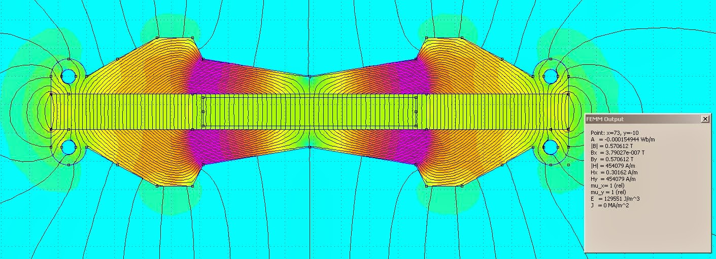
Still maintaining a strong flux density of 0,57 T.
Thanks again Bernt, for this brilliant notion that will save a whole lot of work.
Still maintaining a strong flux density of 0,57 T.
Thanks again Bernt, for this brilliant notion that will save a whole lot of work.
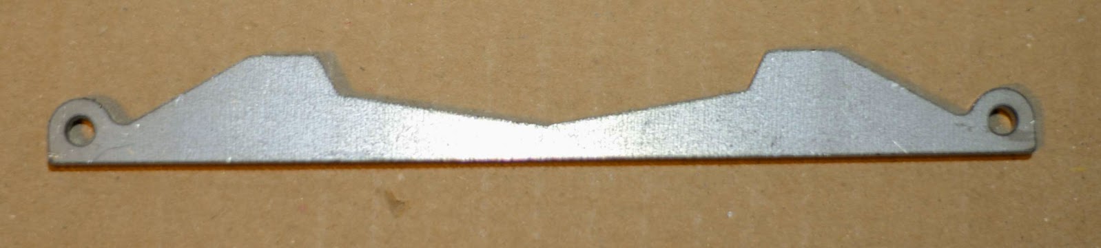
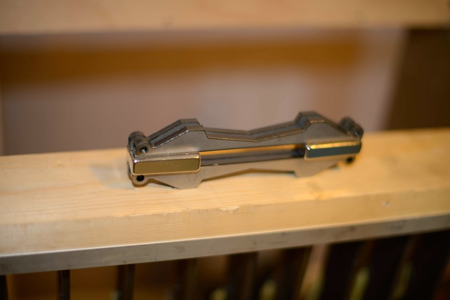
It was the final motor. Got a good price for laser cut pole pieces so I will order soon.
3D views of the finished motor:
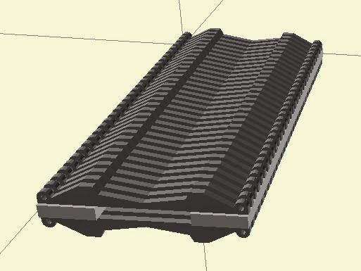

The pole pieces on the back, except the two at the ends, will not be glued to the magnets.
With one mounting rod out, the pole pieces can be turned away with the remaining mounting rod acting as a hinge.
The materials for one 320 mm high motor will cost about SEK 2250 (EURO 225, $250),
Total cost for one 320 mm AMT will be about SEK 3000 (EURO 300, $340).
320 mm high? Well, with these pole pieces one can build a really tall AMT.
Did somebody say line array? Nah, I will not go down that road again...
3D views of the finished motor:
The pole pieces on the back, except the two at the ends, will not be glued to the magnets.
With one mounting rod out, the pole pieces can be turned away with the remaining mounting rod acting as a hinge.
The materials for one 320 mm high motor will cost about SEK 2250 (EURO 225, $250),
Total cost for one 320 mm AMT will be about SEK 3000 (EURO 300, $340).
320 mm high? Well, with these pole pieces one can build a really tall AMT.
Did somebody say line array? Nah, I will not go down that road again...
Looks good. What about an MTM design to increase the low frequency SPL?
Btw, how do you calculate the max SPL of an AMT? I suppose you can't consider the entire diaphragm area as effective driver area. I mean the displacement varies across the surface, right?
Btw, how do you calculate the max SPL of an AMT? I suppose you can't consider the entire diaphragm area as effective driver area. I mean the displacement varies across the surface, right?
Thanks.Looks good.
Hopefully will the new membrane have better SPL, or should I say lower distortion. But if you mean other than an AMT as "M", I don't really need that as the TD15H with their phase plug well covers that should I want to only have the AMT as a "T".What about an MTM design to increase the low frequency SPL?
The membrane has an area of 192 cm2. The ratio is 4,33, so the Sd area is almost as a 15-incher's.Btw, how do you calculate the max SPL of an AMT? I suppose you can't consider the entire diaphragm area as effective driver area. I mean the displacement varies across the surface, right?
With 1,5 mm wide pleats, the theoretical Xmax is half that, that is 0,75 mm. But I suspect that the membrane breaks up long before that. Let's say usable Xmax is 0,25 mm.
If this calculator can be used, that will give an SPL of 110 dB at 1 m @250 Hz.
But I doubt that it is the whole truth. I have 105 dB at 1 W /1 m with my current AMTs, and I cannot detect any motion of the pleats even when I play louder.
I meant an MTM setup of AMT's to extend the range even more. It should be pretty easy to create a vertically segmented AMT, right?Hopefully will the new membrane have better SPL, or should I say lower distortion. But if you mean other than an AMT as "M", I don't really need that as the TD15H with their phase plug well covers that should I want to only have the AMT as a "T".
That's pretty impressive considering the modest size. An ESL panel with the same SPL would have considerably bigger footprint (disregarding the AMT magnet structure).The membrane has an area of 192 cm2. The ratio is 4,33, so the Sd area is almost as a 15-incher's.
With 1,5 mm wide pleats, the theoretical Xmax is half that, that is 0,75 mm. But I suspect that the membrane breaks up long before that. Let's say usable Xmax is 0,25 mm.
Then there are two options.I meant an MTM setup of AMT's to extend the range even more. It should be pretty easy to create a vertically segmented AMT, right?
Several membranes within the same motor or several characteristics within the same membrane.
The first one would require yet another set of amplifiers and DAC channels.
As I am using an USB DAC and want 96/24, I am confined to only have four channels.
For the second one I think it is better to make the best membrane you can make and then EQ what is missing.
Different technology; an AMT is not a magnetostatic panel nor a electrostatic one.That's pretty impressive considering the modest size. An ESL panel with the same SPL would have considerably bigger footprint (disregarding the AMT magnet structure).
Hi Solhaga,
It looks very promissing indeed - really impressive work🙂.
I have a few questions, that I hope you will respond to:
1. Do you have any idea about the approximate Qt of your AMTs (both the 'old' version and the one you are about to make)?
2. Do you consider any drawbacks (except cost!) for using 2 vertically stacked AMTs?
3. Have you considered putting these giant AMTs into production? I have not heard your version, but having heard the difference in resolution and clarity of a large mid AMT driver in the 300-600 Hz range relative to a high quality conventional cone driver, I am pretty sure there would be a marked for these🙂.
Please keep up the good work!
Best regards
Peter
It was the final motor. Got a good price for laser cut pole pieces so I will order soon.
3D views of the finished motor:
The pole pieces on the back, except the two at the ends, will not be glued to the magnets.
With one mounting rod out, the pole pieces can be turned away with the remaining mounting rod acting as a hinge.
The materials for one 320 mm high motor will cost about SEK 2250 (EURO 225, $250),
Total cost for one 320 mm AMT will be about SEK 3000 (EURO 300, $340).
320 mm high? Well, with these pole pieces one can build a really tall AMT.
Did somebody say line array? Nah, I will not go down that road again...
Hi Solhaga,
It looks very promissing indeed - really impressive work🙂.
I have a few questions, that I hope you will respond to:
1. Do you have any idea about the approximate Qt of your AMTs (both the 'old' version and the one you are about to make)?
2. Do you consider any drawbacks (except cost!) for using 2 vertically stacked AMTs?
3. Have you considered putting these giant AMTs into production? I have not heard your version, but having heard the difference in resolution and clarity of a large mid AMT driver in the 300-600 Hz range relative to a high quality conventional cone driver, I am pretty sure there would be a marked for these🙂.
Please keep up the good work!
Best regards
Peter
Thank you, Peter.
1. No I haven't really. Do you have any suggestion on how to measure or estimate it?
2. I will not be using two vertically stacked AMTs. There will always be a distance between two AMTs that will cause combing.
3. No, I haven't. I wouldn't publish on the foras if I were. The AMTs are driven totally active, all signal processing is done in the computer including possible EQ and that then feeds one separate DAC channel and amplifier.
It would be very hard to make a commercial mid range or full range AMT without that as you then must make the whole loudspeaker including filter.
So far it is only the pole piece that is fixed, with it a smaller or larger AMT can be built.
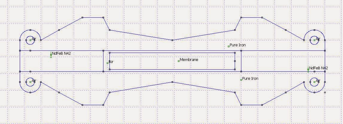
The only thing that is not changeable is the distance between the pole pieces, 10 mm, as they are optimized for that distance.
Hi Solhaga,
Thanks for responding!
I do not know how to measure t/s-parameters, but from a friend of mine whoe does, I know that measuring t/s-parameters on AMTs can be a challenge, partly because they typically do not have a prominent Fs (often only a slight impedanse 'bump'). I also ask because using a waveguide typically requires a fairly strong motor (low Qt), and I know that some of the comercially available AMTs have a very high Qt (e.g., the Dayton AMTPO-4 has a Qt = 4.95 - it's not a dot-error🙂).
Regarding a possible commercial version, I was not thinking about a complete speaker, but only about a driver for the DIY community, but I fully understand and respect your personal take on this! As previously stated: Please keep up the good work and keep us posted - thanks!
Best regards
Peter
Thank you, Peter.
1. No I haven't really. Do you have any suggestion on how to measure or estimate it?
2. I will not be using two vertically stacked AMTs. There will always be a distance between two AMTs that will cause combing.
3. No, I haven't. I wouldn't publish on the foras if I were. The AMTs are driven totally active, all signal processing is done in the computer including possible EQ and that then feeds one separate DAC channel and amplifier.
It would be very hard to make a commercial mid range or full range AMT without that as you then must make the whole loudspeaker including filter.
So far it is only the pole piece that is fixed, with it a smaller or larger AMT can be built.
The only thing that is not changeable is the distance between the pole pieces, 10 mm, as they are optimized for that distance.
The CD waveguide shouldn't pose any considerable load to the driver. It is really only there to pick up some 4-5 dB in the LF. But it could be good to know the Qts should one want to load a horn.Hi Solhaga,
Thanks for responding!
I do not know how to measure t/s-parameters, but from a friend of mine whoe does, I know that measuring t/s-parameters on AMTs can be a challenge, partly because they typically do not have a prominent Fs (often only a slight impedanse 'bump'). I also ask because using a waveguide typically requires a fairly strong motor (low Qt), and I know that some of the comercially available AMTs have a very high Qt (e.g., the Dayton AMTPO-4 has a Qt = 4.95 - it's not a dot-error🙂).
I think the pole pieces are better manufactured locally.Regarding a possible commercial version, I was not thinking about a complete speaker, but only about a driver for the DIY community, but I fully understand and respect your personal take on this! As previously stated: Please keep up the good work and keep us posted - thanks!
Also the magnets should be purchased individually.
Membranes are perhaps another matter, but the 74 film is not cheap and there are a lot of steps to get a finished membrane.
If any of you want FEMM-files or DXF-files or Silhouette-files, you can PM me your mail address and I'll send them to you.
Hi Solhaga,
Thanks for your reply! I am sure there has been a lot of work going into this. Thanks for sharing the development so far🙂. I may get back to you at a later point in time regarding the files.
Best regards
Peter
Thanks for your reply! I am sure there has been a lot of work going into this. Thanks for sharing the development so far🙂. I may get back to you at a later point in time regarding the files.
Best regards
Peter
A little elaboration on membrane design criteria
With V-shaped bottom a forward/backward (that is z-direction) motion is generated modulated by the input signal as the side is straightened when signal is applied.
With U-shaped bottom that are stiff or relatively heavy, the side will be shorter as it now leans toward its counter side. The sides will also tend to close like a clam and thus hinder or compress the sound wave.
A completely parallell movement of the pleat's sides in the x-direction is then the design goal.
So the bottom should be soft and compliant but yet stiff enough in order to keep the shape, that is the two plean sides apart. It is like a speaker surround in micro format.
So my notion of having a heavier or stiffer bottom by adding an aluminium strip is wrong.
Instead I should make the bottom weaker, thinner.
Not changing the material, that is the 74 film, how does one accomplish that?
Sand the bottoms?
Interesting points. I don't have a good mental picture of how the diaphragm moves in an AMT when producing a sound wave. Are there any good descriptions available online?


Ha, ha!
I discovered Heil tweeter very late in my career and I don't understand why it is not better known as it is ideal for classical music! 🙁
I wish to add the AE woofer soon...
Greetings,
M.
I discovered Heil tweeter very late in my career and I don't understand why it is not better known as it is ideal for classical music! 🙁
I wish to add the AE woofer soon...
Greetings,
M.
- Status
- Not open for further replies.
- Home
- Loudspeakers
- Planars & Exotics
- Yet another DIY AMT