Side by side
So with 5 mm iron rods across the two sets of Neos I have to have 5 mm space between the rods in order to let the sound produced o be heard.
The space that can be filled is on the Neos only.
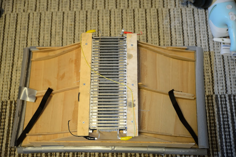
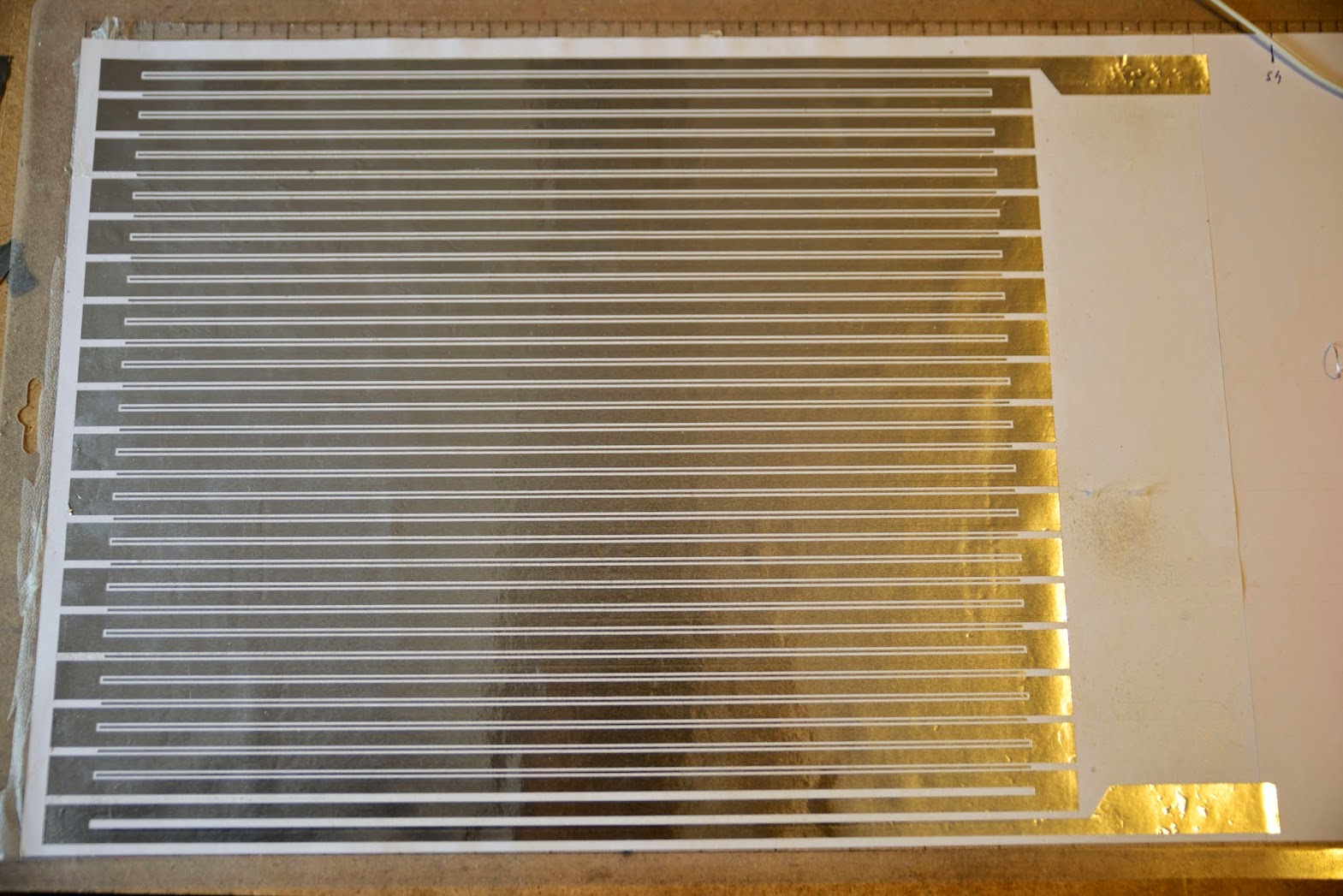
Here an old picture with 5 by 5 mm rods across:
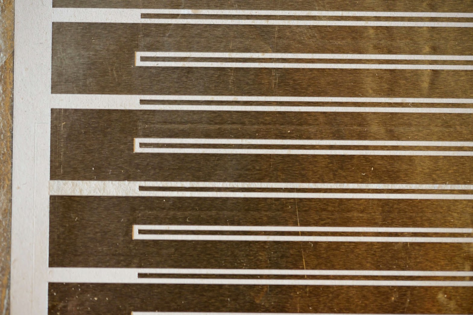
The rods will now be more like:
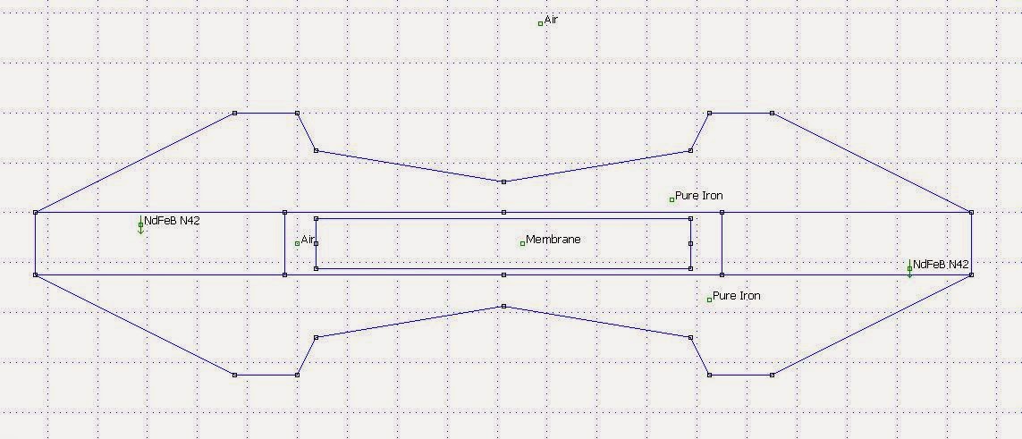
FEMM is not 3D, but as a comparison I have simulated side views with no spacers, 5 mm iron spacers and 10 mm iron spacers.
The goal is to get as high and evenly distributed flux as possible though all the 20 mm rods that are across the gap. The flux is measured on the second rod.
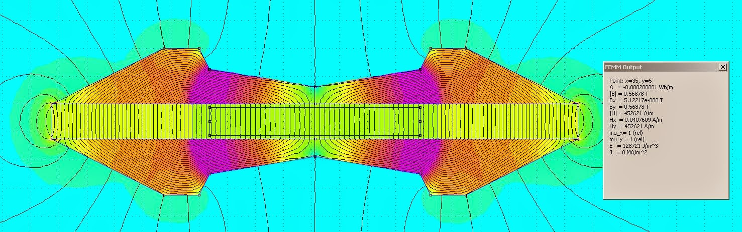
No spacers:


5 mm spacers:


10 mm spacers:


My conclusion is that there should be no spacers, at least not made of iron.
To support the rods though, I will have spacers made of aluminium.
So with 5 mm iron rods across the two sets of Neos I have to have 5 mm space between the rods in order to let the sound produced o be heard.
The space that can be filled is on the Neos only.
Here an old picture with 5 by 5 mm rods across:
The rods will now be more like:
FEMM is not 3D, but as a comparison I have simulated side views with no spacers, 5 mm iron spacers and 10 mm iron spacers.
The goal is to get as high and evenly distributed flux as possible though all the 20 mm rods that are across the gap. The flux is measured on the second rod.
No spacers:
5 mm spacers:
10 mm spacers:
My conclusion is that there should be no spacers, at least not made of iron.
To support the rods though, I will have spacers made of aluminium.
If I'm correct about my assumption on the resulting HH, the frequency response in the HF will be better as well as the rubber, or whatever compound I will try, makes the HH more shallow.Otherwise a syringe could do the trick to get the rubber to the bottom.
So with 5 mm iron rods across the two sets of Neos I have to have 5 mm space between the rods in order to let the sound produced o be heard.
The space that can be filled is on the Neos only.
Here an old picture with 5 by 5 mm rods across:
The rods will now be more like:
FEMM is not 3D, but as a comparison I have simulated side views with no spacers, 5 mm iron spacers and 10 mm iron spacers.
The goal is to get as high and evenly distributed flux as possible though all the 20 mm rods that are across the gap. The flux is measured on the second rod.
No spacers:
5 mm spacers:
10 mm spacers:
My conclusion is that there should be no spacers, at least not made of iron.
To support the rods though, I will have spacers made of aluminium.
highest field without spacers, but does an even field make any difference ? because with the small rods the field is a bit more even.
You have to think that the usable flux in the rods across, that is the ones that are 20 mm high, is into the paper's plane.
So the simulation without any iron rods has the most even flux for the seven rods.
So the simulation without any iron rods has the most even flux for the seven rods.
Finally got around to some cad work.
I'm still struggling with the learning curve of FreeCAD so here's the programatic OpenSCAD instead.
Two views of a finished AMT. No membrane, though.
It is 320 mm high and 140 mm across. Depth is 50 to 20 mm.

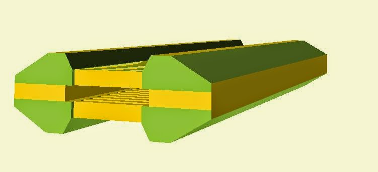
I haven't decided if the membrane shall be 60 or 50 mm.
It depends on how well I manage to put two pieces of aluminium foil together.
I need almost 320 mm of unfolded foil but the machine only takes 300 mm (that is: 12 ")
I will be alright with a 50 mm folded membrane, I can always let the waveguide begin in the AMT itself.
50 mm would also mean higher flux density and the resistance would be less, I'm struggling to get under 8 ohms.
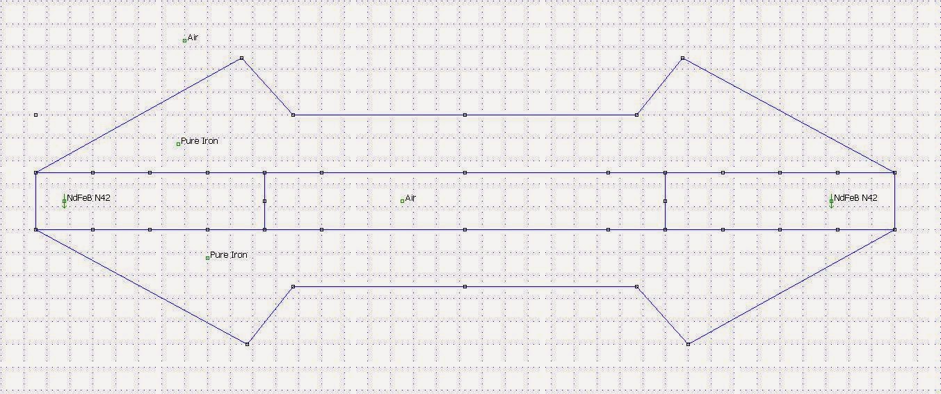
Simulations: still using the ideal "Pure Iron", but here's one that yield 0,62 T in the gap:

I'm still struggling with the learning curve of FreeCAD so here's the programatic OpenSCAD instead.
Two views of a finished AMT. No membrane, though.
It is 320 mm high and 140 mm across. Depth is 50 to 20 mm.
I haven't decided if the membrane shall be 60 or 50 mm.
It depends on how well I manage to put two pieces of aluminium foil together.
I need almost 320 mm of unfolded foil but the machine only takes 300 mm (that is: 12 ")
I will be alright with a 50 mm folded membrane, I can always let the waveguide begin in the AMT itself.
50 mm would also mean higher flux density and the resistance would be less, I'm struggling to get under 8 ohms.
Simulations: still using the ideal "Pure Iron", but here's one that yield 0,62 T in the gap:
So I need to put two aluminium foils together to get a 320 mm by 60 mm finished membrane:

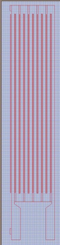
Close up showing the piece of unconnected aluminium foil that I intend to keep at the bottom of each pleat.
It will of course have the rubber under it as well.
So perhaps the "hinge" will be stiffer that way.

The aluminium in the circuit is 5,5 mm and the space is 2,5 mm.
Folding will be 6,5/1,5 mm.
Close up showing the piece of unconnected aluminium foil that I intend to keep at the bottom of each pleat.
It will of course have the rubber under it as well.
So perhaps the "hinge" will be stiffer that way.
The aluminium in the circuit is 5,5 mm and the space is 2,5 mm.
Folding will be 6,5/1,5 mm.
I think it will be hard to merge the two aluminium cut-outs into one.
I did one for a 50 mm membrane that yielded about 6 ohms, so I will stick to that width.
Close up on the 1 mm not connected aluminium strip at the bottom of each pleat:
Further simulations where I tried to remove the "green fields" resulted in this:


Any ideas if this will be acoustically better or any suggestions on what to change?
I did one for a 50 mm membrane that yielded about 6 ohms, so I will stick to that width.
Close up on the 1 mm not connected aluminium strip at the bottom of each pleat:
Further simulations where I tried to remove the "green fields" resulted in this:
Any ideas if this will be acoustically better or any suggestions on what to change?
Alter the shape of the aperature edge from facets to a roundover of appropriate radius. Liked the clipping of that sharp (dead) peak in this last femm iteration, but think this would be better acoustically. Also appears you could shorten the width by chopping a bit off the ends. Cannot tell from this but outside width would shorten to 125mm or so.
Impressive pattern, well thought out. 🙂
Impressive pattern, well thought out. 🙂
The membrane is in the center 50 mm so what's going on outside that is only for the field build up and distribution. It doesn't affect the actual sound wave. But it could be good to do it anyway.Alter the shape of the aperature edge from facets to a roundover of appropriate radius.
Then the iron will not cover the Neos.Also appears you could shorten the width by chopping a bit off the ends. Cannot tell from this but outside width would shorten to 125mm or so.
From the left there is a 40 mm Neo, 5 mm frame, 50 mm membrane, 5 mm frame, 40 mm Neo.
Look at picture in post #361 and the drawings in #365.
Thanks, just looked for the green fields.Impressive pattern, well thought out. 🙂
See what you are saying about the neo's. Shame we can't get everything exactly like we want. 😉
The rounding would help the wavefront propogation. With the amt's I have the chamfered bezel has been removed and replaced with a waveguide to help support it's low end response around 2k. Not only does this lift the bottom up but also reduces distortion in that area of operation. Only thinking similar would be helpful, if anything diffraction would be reduced.
The rounding would help the wavefront propogation. With the amt's I have the chamfered bezel has been removed and replaced with a waveguide to help support it's low end response around 2k. Not only does this lift the bottom up but also reduces distortion in that area of operation. Only thinking similar would be helpful, if anything diffraction would be reduced.


Thanks Bernt. Then there's four equal parts.
But I must have a bar between the two row of magnets.
But I must have a bar between the two row of magnets.
If you use a holder like this.Skærestandere 230 mm Einhell TS 230 230 mm - - Vinkelsliber - Værktøj - Conrad Elektronik
You can cut them from a 5x15mm bar or 5x20mm bar
You might have have to weld the points together before asembling
Bernt
An externally hosted image should be here but it was not working when we last tested it.
You can cut them from a 5x15mm bar or 5x20mm bar
You might have have to weld the points together before asembling
Bernt
Got one of those, so it might be worth a try.
Also got this today: Dremel DSM 20.
With that I can make a folding tool by sawing 6,5 mm deep and 1,5 wide cutouts 3 mm apart in a oak plank.
The Dremel can also be used for fine tuning of the bars.
Still haven't given up on having them laser cut.
Also got this today: Dremel DSM 20.
With that I can make a folding tool by sawing 6,5 mm deep and 1,5 wide cutouts 3 mm apart in a oak plank.
The Dremel can also be used for fine tuning of the bars.
Still haven't given up on having them laser cut.
I might do this one:
 [/url][/IMG]
App. 0,54t in field
Bars in between made from steel or alu to make a kind of horn.
Bernt
App. 0,54t in field
Bars in between made from steel or alu to make a kind of horn.
Bernt
I would advice against to have spacers made of steel, see pos #361.I might do this one:
[/url][/IMG]
App. 0,54t in field
Bars in between made from steel or alu to make a kind of horn.
Bernt
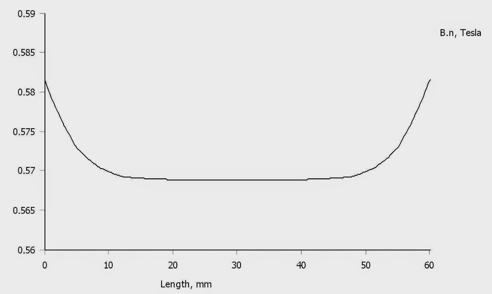
Final motor
So this is the final motor?
I pulled the magnets apart by 10 mm, so that a 60 mm membrane can fit as well.
If the 50 mm was 6 ohms, then a 60 mm should be 7,2 ohms.
Flux will only be a little bit (10 %) weaker but I will have 20 % more of membrane area.
Flux density is 0,575 T +/- 1 %
So this is the final motor?
I pulled the magnets apart by 10 mm, so that a 60 mm membrane can fit as well.
If the 50 mm was 6 ohms, then a 60 mm should be 7,2 ohms.
Flux will only be a little bit (10 %) weaker but I will have 20 % more of membrane area.
Flux density is 0,575 T +/- 1 %
You could make 2 ø5mm holes (lasercut) , to assemble the unit with 5mm threaded rod.
 [/url][/IMG]
I did that with the "kithara" model
Bernt
I did that with the "kithara" model
Bernt
- Status
- Not open for further replies.
- Home
- Loudspeakers
- Planars & Exotics
- Yet another DIY AMT