That would be very hard to accomplish considering that I have a two way system.You should also have a clean mids speaker I think. I use Saba Greencone between midbass and Beyma TPL-150.
Yes, that´s why I don´t need a three or four way system.
In fact, I do not even consider anything other than a two way system.
In fact, I do not even consider anything other than a two way system.
Seems that I thought that the post was directed to me, obviously it was a comment on maxlorenz´post. Sorry about the confusionYou should also have a clean mids speaker I think. I use Saba Greencone between midbass and Beyma TPL-150.
 .
.It's all about compromises...
When I return to my full-range corner front and back-loaded horns with cheap Audio Nirvana transducers varnished with Dammar, I miss some of the bass impact but I am immediately seduced by the coherency and rich tonality...
That said, I've never listened to a 3way with extended range mid transducer. That would require a three way active XO for me... 🙁
Sorry for OT.
Best wishes,
M.
60 st steel rulers for the new folding tool:

They are 1,0 mm so I need to have 0,5 mm spacers made of 0,5 mm PFTE sheet.
They are 1,0 mm so I need to have 0,5 mm spacers made of 0,5 mm PFTE sheet.
They are 1,0 mm so I need to have 0,5 mm spacers made of 0,5 mm PFTE sheet.
Or make the pockets 1 mm and 2 mm in some smart distribution.
The pockets facing backward will always be 1 mm.
For each membrane the depth must be the same though, 8 mm being the maximum.
The membrane can be easily designed:
Draw it programmatic-ally in SCAD-format in OpenSCAD and export a dxf file.
Import the dxf file to Silhouette Design Studio and send to Cameo cutter.
Something like this.
solhaga, again no half way of doing things as usual 🙂 your laser cut iron looks stunning! verry verry profesional. also since you got all drawings when ever you decide its a winner you order more and costs go down. it could even be a verry nice DIy product. but i always sense thats not ur end goal. (i always dream of living of the thing i really like to do)
 and
and  and then
  .
.The surface on the pole pieces where the magnets are isn't even.
It is less than 0,1 mm irregurality though.
Did some simulations on this and a 0,1 mm gap results in a 0,35 % less field strength where the membrane is.
That is much less that the 2,5 % the field varies across the membrane.

So I just sand down the worst.
It is less than 0,1 mm irregurality though.
Did some simulations on this and a 0,1 mm gap results in a 0,35 % less field strength where the membrane is.
That is much less that the 2,5 % the field varies across the membrane.
So I just sand down the worst.
Or make the pockets 1 mm and 2 mm in some smart distribution.
The pockets facing backward will always be 1 mm.
For each membrane the depth must be the same though, 8 mm being the maximum.
The membrane can be easily designed:
Draw it programmatic-ally in SCAD-format in OpenSCAD and export a dxf file.
Import the dxf file to Silhouette Design Studio and send to Cameo cutter.
Something like this.
Been thinking a little bit more on this.
For a pocket 2 mm wide and let's say 8 mm deep in order to make it easier to "calculate", the folding ratio is 4. Xmax should be better, at least until there's a break-up.
But the same Xmax cannot be allowed for the 1 mm wide pocket, and it has a folding ratio of 8.
So there's a need to make the movement smaller for the smaller pocket.
One idea is then to have a narrower conductor for the 2 mm pocket, perhaps 4 mm, and a wider for the 1 mm pocket, perhaps 6 mm.
Still the same current, but a weaker electric field in the magnetic field and thus a smaller force on that pleat.
Having a 4 mm conductor on the 2 mm wide but 8 mm deep pocket would also mean that breakup comes at a higher X.
That the narrower hf pockets should be in the middle is another assumption, thereby minimizing any possible comb effect.
Also considering the smaller dispersion in the wave guide.
So then it all should be about getting the correct ratio for the 2 mm and 1 mm pockets and the sum of them for the 1 mm "back" pockets.
Wide x 2 + Narrow x 1 + Wide x 2 + (Narrow + 2 x Wide) = 60 mm
With Wide = 7 and Narrow = 9 one will get: 14 + 9 + 14 + 23 = 60 mm
After have sanded the surface it is time to start to assemble:
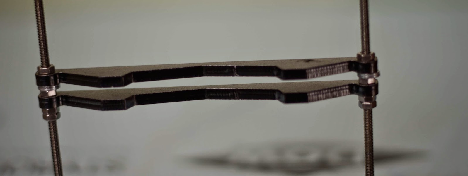
2 down, 30 to go:
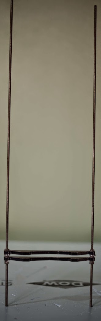
I guess I should have started at the middle...
2 down, 30 to go:
I guess I should have started at the middle...

After writing the reply below to your post, phazer99, I realized that it might be thought of as a little grumpy.
Sorry for that.
One of the reasons for showing the progress at almost real time is to get a "couldn't you" instant feedback instead of a "you should have" when I'm finished.
My comment "I guess I should have started at the middle..." actually forced me do to so when I read this after posting it. But it could just as well been a response from a forum member.
Another reason is to have the procedure documented and perhaps inspire others to build AMTs, it is after all really easy.
I've finished the first AMT's front pole pieces without any blisters and it is now time to mount the first magnets. Perhaps there will be some pictures later today.
Stay tuned if you want to see it.
Oh, lucky I didn't even read your first respons then 🙂
I didn't mean to be sarcastic or anything, I just thought your comment was funny as I can understand the tedious process of assembling the AMTs. I follow your project with great interest (even though I don't have enough knowledge to contribute with any useful comments) and hope it will be successful as I find AMTs to be one of the few viable alternatives to ESL's for my DIY projects (with the advantage of smaller size).
So, please keep the progress reports coming
Last edited:
Yeah. We are all  and sending you the good vibrations, even if we can't contribute with any more tangible help...
😀
Best wishes,
M.
and sending you the good vibrations, even if we can't contribute with any more tangible help... 😀
Best wishes,
M.
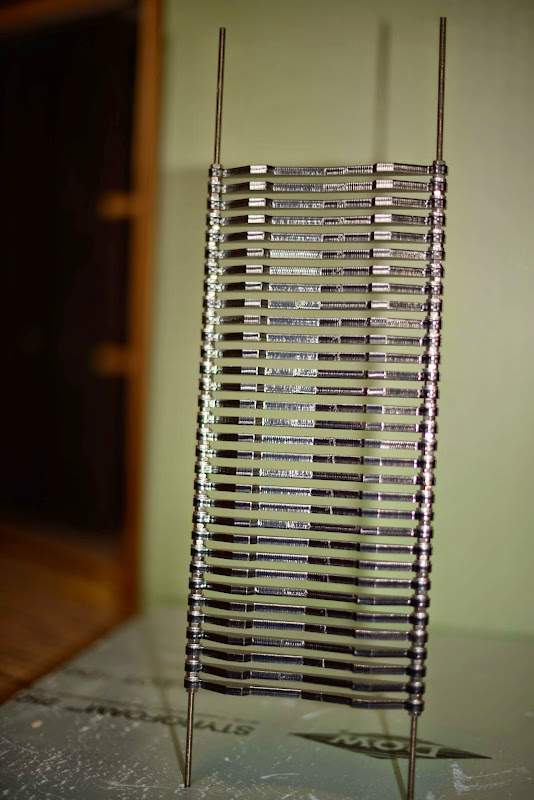
Front grid finished:
A couple of wood pieces constitutes a mounting help:

First couple of Neos was easy:

Second row is a little bit trickier, have to slide it down from a safe distance:

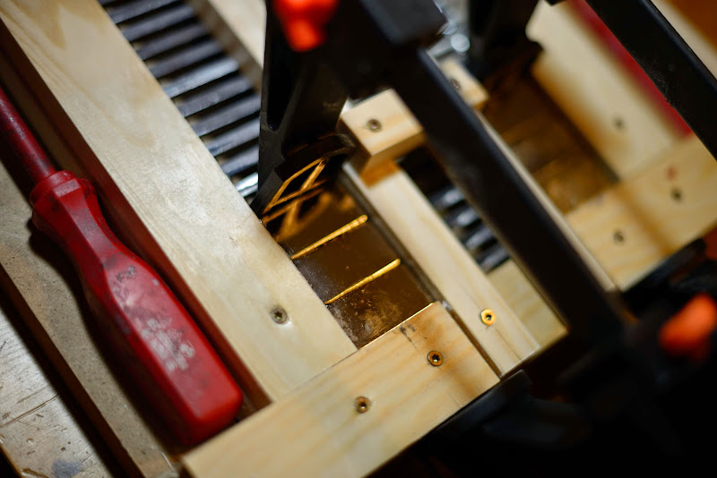
But got them in the right place with a pair of clamps:


Will they remain after the glue has cured?
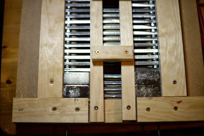
Yes!
Third row:
It´ll have to be a couple of hours between the rows, but I will get there.
A couple of wood pieces constitutes a mounting help:
First couple of Neos was easy:
Second row is a little bit trickier, have to slide it down from a safe distance:
But got them in the right place with a pair of clamps:
Will they remain after the glue has cured?
Yes!
Third row:
It´ll have to be a couple of hours between the rows, but I will get there.
Last edited:
ai yeha you need to force them in ofcourse. thats some work 🙂 Looking goood!! following this thread!. i still want to do buy a plotter to 🙂 to try this for once 🙂
having larger magnets would saved you some time ? but maybe impossible to force in hmmmm every upside has his down 🙁
having larger magnets would saved you some time ? but maybe impossible to force in hmmmm every upside has his down 🙁
First motor assembled
Last magnets in place:

And they are still there after the clamps have been removed:

That has not always been the case, 5 or 6 times has the magnet snapped away when the clamps has been removed.
Bare magnets ready for the pole pieces. Better secure the last row before start to mount them:

2 mm and 3 mm aluminium rods from old folding tools provides the necessary spacing while mounting and gluing:

Cannot have spacers and nuts, so it is only the bare nut thread between the pole peices:

Move all the spacing to one side in order to get to fill one side with epoxy:


Swaps sides and repeat.
Glued an 25 mm aluminium rod on the sides:

An "artistic" view:

Bottoms up, or was it the other way around:

I put epoxy also between the pole pieces on the front together with a piece of 5 mm EPDM sealing. The latter in order not to get any leakage of the front going sound pressure wave.
Final motor with EPDM sealing on the front, this should reduce vibrations when mounting it on the wave guide::

So the 66x10 mm gap, 320 mm deep, is ready for the membrane:

Final motor from another angle:

It's time to get serious on the folding tool, I've got some ideas that looks promising...
Last magnets in place:
And they are still there after the clamps have been removed:
That has not always been the case, 5 or 6 times has the magnet snapped away when the clamps has been removed.
Bare magnets ready for the pole pieces. Better secure the last row before start to mount them:
2 mm and 3 mm aluminium rods from old folding tools provides the necessary spacing while mounting and gluing:
Cannot have spacers and nuts, so it is only the bare nut thread between the pole peices:
Move all the spacing to one side in order to get to fill one side with epoxy:
Swaps sides and repeat.
Glued an 25 mm aluminium rod on the sides:
An "artistic" view:
Bottoms up, or was it the other way around:
I put epoxy also between the pole pieces on the front together with a piece of 5 mm EPDM sealing. The latter in order not to get any leakage of the front going sound pressure wave.
Final motor with EPDM sealing on the front, this should reduce vibrations when mounting it on the wave guide::
So the 66x10 mm gap, 320 mm deep, is ready for the membrane:
Final motor from another angle:
It's time to get serious on the folding tool, I've got some ideas that looks promising...
- Status
- Not open for further replies.
- Home
- Loudspeakers
- Planars & Exotics
- Yet another DIY AMT