OK guys, few developments here. My bench now includes a BK Precision 1655A power supply and a matching BK 2190D oscilloscope. I'm counting on your collective knowledge to turn these into something meaningful in my untrained hands! (if at all possible)
I performed the resistance measurement suggested by cogeniac and came up with a very stable 3.64M ohms on the "red side" and 1.6M ohms on the "orange side" that continuously drops until it settles at about 1.47M ohms.
I haven't tried bringing up on the variac yet because I'm not sure what I'm looking for when I do. With the big input resistor shorted are we simply looking for the relay to close (assuming we've removed any shorted output components) ?
Hi maceoc3,
Absolutely not! You have found exactly what I knew you were going to find.
Short the dead resistor - I don't care how you do it. If you must because you do not have a variac, set up a lamp socket in series with an outlet and stick a low wattage lamp in it. Plug the amp in and turn it on. The lamp will be near full brilliance I'm guessing. Measure from the speaker output terminal (Red) to each power supply rail in turn. One channel will show zero voltage difference between the speaker output and one of the supply voltages.
Alternate test. Power off and unplugged - discharged completely. Most DVMs will also check this using diode check (higher output current than resistance testing). Without knowing your meter I don't want to make any assumptions about it. Look for a very low to short reading between the speaker output and each power supply. Do make sure the speaker fuses are okay before trying this.
-Chris
Performed both of these tests with the following results: With the resistor shorted and the variac at about 10 volts I get .199 V across one side (orange) and 4.33 V on the other (red).
Using the diode check function on my meter the red side starts at .646 V and climbs to about 1.310 V in thirty seconds or so and the orange side starts at .376 V and climbs to .410 V. Both will continue to climb, red more so than orange.
The variac does not like this at all- I can't even get to 20 volts before popping the fuse in the variac. Like something is dead shorted somewhere.
Looks to me like the negative (orange side is shorted).
Did you measure the resistance from the rails to ground, using BOTH polarities? Try that test again and then reverse the leads and do it again...Make sure you measure from the DC rail strap on the output board to the ground strap.
If those measurements really show megohms, then there is no output short per se. In this case I'd suspect that the bias on the transistors is such that both sides are conducting at the same time. However, your voltage measurements indicate a short on the negative side.
To check if the outputs are shorted hard (as in a bad transistor) vs shorted soft (as in bad bias), disconnect the brown and blue wires that attach to points 3 and 4 on the control board (in the middle of the board). Then turn on the amp. If the amp powers up OK with these disconnected, then the problem is that the output of the control board is biasing both positive and negative output banks on at the same time. I have seen this on several amps.
If this has no effect, then you have one or more shorted output transistors (which, honestly sounds like the case based on your voltage measurements, and the variac popping fuses at only 20 volts).
Remember the output transistors each have 0.33 ohms in the emitter leg. It is hard to say what the DC rails were doing with 10 volts AC at the transformer primary, but if we assume things scale linearly, then 100 volts AC produces about 85 volts DC at the rails, so 10 volts should produce (10/120)*85=7 volts at the DC rails. you are measuring 0.2 volts, so clearly something is rotten on the orange side of Denmark...
You will need one more piece of equipment. Some sort of audio signal source. You can use any audio source, or you can beta function generator (generates square waves, saw tooth waves, triable waves and sine waves over a wide renege of frequencies. I have a BK unit I got from Fry's years ago for about $120. You can even find DIY board based function generators for about $5 on eBay...This allows you to input as known signal to the amp, and then trace it through the various gain stages. eBay seems to have these in many varieties, with actual lab units starting at around $100.
Last edited:
Performed multiple resistance measurements last night but upon re-reading your instructions today, I realize I wasn't doing it correctly- forgot to disconnect the feeds to the power rails for the measurement so my results were all over the place.
I did disconnect the input board per your suggestion with no change in behavior. Earlier in the discussion you suggested disconnecting the power to both output stages as a quick check for shorts there. I did this again and with both feeds disconnected as well as the connection from the input board, the amp still is dead shorted somewhere. This test effectively eliminates the output stages, right?
Could the transformer be shorted?
Hmmm. Interesting...
Given these results, probably the easiest way to isolate the short is to start at the power supply.
First, remove the two fuses on the back that have the recessed screw-in fuse holders.
These feed the output stages and also the current source section of the control board (terminals 6 and 10 on the control board)
Try powering the amp. If it powers-on with the fuses removed, then you have a short in either the output section or the control board current source (unlikely). If it still fails to power on, then the problem is either in the control board, the transformer, the caps or the bridge rectifier.
You will notice that there are several orange and red wires that connect to the big blue caps with screws. One red wire goes to terminal 5 on the control board and an orange wire goes to terminal 11 on the control board, and the others are as described above. With the amp off, check the voltages at the red and orange wires to ground - to be sure the caps are discharged.
Then disconnect the wires, and tape them so they don't flop onto the cap terminals by accident.
With all of these disconnected, try powering the amp. If it turns on, then the problem is on the control board. If it fails to power on, then the problem is either the caps or the bridge. If the caps were shorting, I'd expect them to explode, so they are probably OK.
With the amp UNPLUGGED, put tape on one of the red wires that attaches to the bridge (this is the square block located between the soft start board and the transformer..way down in the bottom of the amp. It has two red wires, a yellow wire and an orange wire. Take a photo of it after you have taped one of the red wires. Make sure the photos shows the corner of the bridge that is angled (this is all so you can put it back together properly). Then disconnect the spade connectors from the bridge and tape them.
At this point only the transformer and the soft start board are connected to the AC line.
Try powering the amp. If it still fails, then I'd suspect the transformer, which would totally suck.. However, the fact that the resistor on the soft start board is blowing tells me that the transformer primary is at least conducting properly.. so I'd doubt the transformer is the culprit.
If it comes on, then check the bridge using your DVM.
Here is the basic bridge circuit.

The terminal at the angled corner is the +V terminal. the terminal opposite this one is the -V terminal. From the schematic above, you can see that the diodes should conduct as follows:
1. With the positive DVM lead connected to one of the AC inputs you should see conductivity wight he ground lead of the DVM connected to +V. If you reverse the leads there should be no conductivity.
2. With the positive DVM lead connected to the OTHER AC input you should also see conductivity with the ground lead of the DVM connected to +V, and reversing the leads should show open.
3. Re peat this test with the red wire of the DVM connected to the _v terminal and the back wire connected to the AC terminals (on and then the other). Reverse the leads and repeat.
If the bridge shows conductivity in one direction but not the other on each of these tests, it should be OK. If it shows conductivity in both directions it is shorted. You can probably confirm this by testing continuity across the AC terminals.
Given these results, probably the easiest way to isolate the short is to start at the power supply.
First, remove the two fuses on the back that have the recessed screw-in fuse holders.
These feed the output stages and also the current source section of the control board (terminals 6 and 10 on the control board)
Try powering the amp. If it powers-on with the fuses removed, then you have a short in either the output section or the control board current source (unlikely). If it still fails to power on, then the problem is either in the control board, the transformer, the caps or the bridge rectifier.
You will notice that there are several orange and red wires that connect to the big blue caps with screws. One red wire goes to terminal 5 on the control board and an orange wire goes to terminal 11 on the control board, and the others are as described above. With the amp off, check the voltages at the red and orange wires to ground - to be sure the caps are discharged.
Then disconnect the wires, and tape them so they don't flop onto the cap terminals by accident.
With all of these disconnected, try powering the amp. If it turns on, then the problem is on the control board. If it fails to power on, then the problem is either the caps or the bridge. If the caps were shorting, I'd expect them to explode, so they are probably OK.
With the amp UNPLUGGED, put tape on one of the red wires that attaches to the bridge (this is the square block located between the soft start board and the transformer..way down in the bottom of the amp. It has two red wires, a yellow wire and an orange wire. Take a photo of it after you have taped one of the red wires. Make sure the photos shows the corner of the bridge that is angled (this is all so you can put it back together properly). Then disconnect the spade connectors from the bridge and tape them.
At this point only the transformer and the soft start board are connected to the AC line.
Try powering the amp. If it still fails, then I'd suspect the transformer, which would totally suck.. However, the fact that the resistor on the soft start board is blowing tells me that the transformer primary is at least conducting properly.. so I'd doubt the transformer is the culprit.
If it comes on, then check the bridge using your DVM.
Here is the basic bridge circuit.
The terminal at the angled corner is the +V terminal. the terminal opposite this one is the -V terminal. From the schematic above, you can see that the diodes should conduct as follows:
1. With the positive DVM lead connected to one of the AC inputs you should see conductivity wight he ground lead of the DVM connected to +V. If you reverse the leads there should be no conductivity.
2. With the positive DVM lead connected to the OTHER AC input you should also see conductivity with the ground lead of the DVM connected to +V, and reversing the leads should show open.
3. Re peat this test with the red wire of the DVM connected to the _v terminal and the back wire connected to the AC terminals (on and then the other). Reverse the leads and repeat.
If the bridge shows conductivity in one direction but not the other on each of these tests, it should be OK. If it shows conductivity in both directions it is shorted. You can probably confirm this by testing continuity across the AC terminals.
Last edited:
Well, I finally got around to stuffing my new control board, and trying it out.
It had a number of smallish issues..
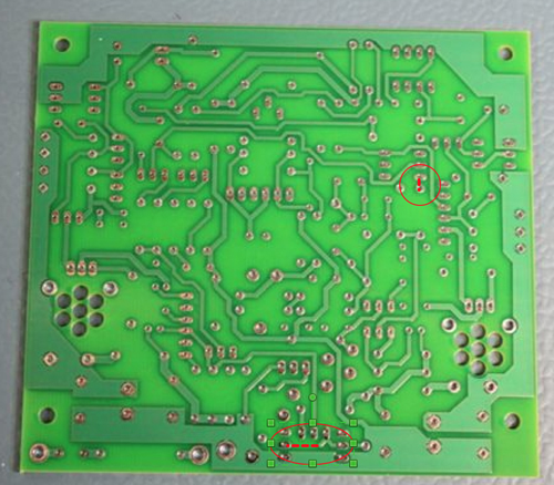
First, when I was editing the layout to fatten up some of the traces, I inadvertently left two different sets of pads disconnected. The Eagle software I used for the PCB layout shows connections that have no traces as light yellow "air wires", and these just happened to be obscured by other lines on the layout. Once I found these I was able to easily jumper across them.
I managed to install the little KB262 diodes backwards. I should have checked them. They are black on one need and colored on the other..dumb mistake, but easily fixed.
The worst issue was that I had grabbed a T092 package layout from a library in Eagle.. and made versions of the various transistors for the schematic and layout (in Eagle each part has a schematic diagram AND a physical layout..When you do the physical layout, you must connect the pads on the layout to the terminals on the schematic so Eagle will know the logical relationship between the schematic version of the part and the physical version). Of course, while most packages in Eagle have the pins labeled left to right, the one I chose happened to number them right to left..This means that every single T092 device was installed 180 degrees out.. In general this wasn't a disaster because what it meant was that, for every device other than the Darlingtons, the base and emitter pins were swapped. Since the Darlingtons are embedded in the chain, and all the transistors were "off" (because they base emitter junctions were all reverse biased, The Darlingtons were also OK.
This silly error required carefully unsoldering every T092 device and rotating it 180 degrees..
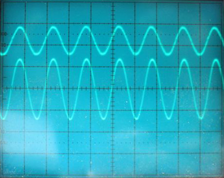
Once that was done (and the diode stacks were fixed), she fired right up. Stable, with zero DC offset. I then hooked up the output stages and took her for a spin. Here are the pics..
Top Trace: Input at 1 volt/div. Bottom trace (centered on zero volts): 50 volt/div.

Same setup but t full power into 8 ohms
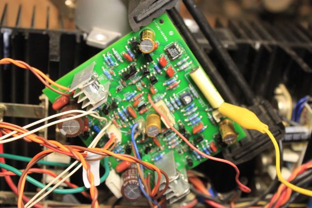
The new board in situ...
And the two trace errors:
I'll correct the board and build up another one sometime in the next few weeks.
Cheers!!
Scott
It had a number of smallish issues..
First, when I was editing the layout to fatten up some of the traces, I inadvertently left two different sets of pads disconnected. The Eagle software I used for the PCB layout shows connections that have no traces as light yellow "air wires", and these just happened to be obscured by other lines on the layout. Once I found these I was able to easily jumper across them.
I managed to install the little KB262 diodes backwards. I should have checked them. They are black on one need and colored on the other..dumb mistake, but easily fixed.
The worst issue was that I had grabbed a T092 package layout from a library in Eagle.. and made versions of the various transistors for the schematic and layout (in Eagle each part has a schematic diagram AND a physical layout..When you do the physical layout, you must connect the pads on the layout to the terminals on the schematic so Eagle will know the logical relationship between the schematic version of the part and the physical version). Of course, while most packages in Eagle have the pins labeled left to right, the one I chose happened to number them right to left..This means that every single T092 device was installed 180 degrees out.. In general this wasn't a disaster because what it meant was that, for every device other than the Darlingtons, the base and emitter pins were swapped. Since the Darlingtons are embedded in the chain, and all the transistors were "off" (because they base emitter junctions were all reverse biased, The Darlingtons were also OK.
This silly error required carefully unsoldering every T092 device and rotating it 180 degrees..
Once that was done (and the diode stacks were fixed), she fired right up. Stable, with zero DC offset. I then hooked up the output stages and took her for a spin. Here are the pics..
Top Trace: Input at 1 volt/div. Bottom trace (centered on zero volts): 50 volt/div.
Same setup but t full power into 8 ohms
An externally hosted image should be here but it was not working when we last tested it.
The new board in situ...
An externally hosted image should be here but it was not working when we last tested it.
And the two trace errors:
An externally hosted image should be here but it was not working when we last tested it.
I'll correct the board and build up another one sometime in the next few weeks.
Cheers!!
Scott
Last edited:
cogeniac,
Congrats on the new board!!
Performed the rail resistance test correctly with these results:
Orange:
COM on - rail = 31.08k ohms
COM on + rail = 5.32M ohms
Red:
COM on - rail = 3.911M ohms
COM on + rail = 30.91k ohms
Performed a power-up with the DC rail fuses removed- no dice.
I haven't done the big cap test as I was little unclear about which wires I was disconnecting- only the small wires going to 5 & 11 or all orange and red wires on the caps?
Went ahead tried disconnecting the rectifier and the amp will accept full power.
The rectifier passes the diode test perfectly.
I'm guessing the transformer is still suspect?
Looks like your outputs are OK...
Hmmm. Not so sure about the transformer......
If the amp powers up with the rectifier disconnected, then the transformer is probably OK. So, if the rectifier checks out, then the issue is after the rectifier.
Try just connecting the AC lines (yellow and red from the transformer) to the rectifier, but leave the orange and red DC lines (that go to the caps) disconnected.If this fails then the rectifier is probably bad, even if it checked out.. or else the transformer has some weird current related fault.
If that works, then find the red and orange wires from the rectifier, and reconnect them to the caps with all of the other red and orange wires disconnected...and try that. If that fails then the caps or the discharge resistors (on the little boards attached to the tops of the caps) are bad.
I PM'ed you about the board
Last edited:
Forgot to mention a couple of other issues with the board...
The three three-pin connectors on the board are, inexplicably, numbered 132, instead of 123..So, you need to pull the contacts out of the three connectors and swap pins 2 and 3.. Also, the layout I used puts the J105 and J106 connectors too close together, so you have to shave off about 25 mils from each connector housing so they
will fit.
My new version fixes these issues.
OK, here we go...
With the DC wires disconnected from the rectifier, amp powers up OK.
With the DC wires reconnected but other orange & red wires disconnected, amp still acts shorted.
All three resistors on cap PCB check out good.
With the DC wires disconnected from the rectifier, amp powers up OK.
With the DC wires reconnected but other orange & red wires disconnected, amp still acts shorted.
All three resistors on cap PCB check out good.
Well!!
OK, so I guess the means that the caps (or one of them) are shorted...With the PC boards removed from the caps, test them with your DVM. They may look shorted for a while until they charge up, but eventually you should see the resistance going up to infinity...
Also, just because one never knows, check the traces on the two cap PC Boards to be sure some joker didn't create a solder bridge or something. You can check this easily with your DVM. With all the wires disconnected, the resistance between the traces around the screw holes should be about 8K. If it is zero, then there is a shorted trace on the board. My amps have resistors on the under sides of the two boards too.
The caps are pretty pricey. I got a set of them for $148 from Digikey. Be certain that this is the problem before dropping the dough on them.
https://www.digikey.com/product-detail/en/nichicon/LNR2A473MSE/493-7698-ND/3930080
Step by step!!
Cheers
Scott
Hi Scott,
Very nice work. I think you made a better PCB than the original was - by far! If I had an Adcom on my bench I would be asking you for some.
One test you should perform is a lower level frequency sweep. What you want to see is a constant output with frequency, then a roll-off to very low output. What you are watching out for is a rise in output level. You may eve provoke some oscillation. If your amplifier looks stable - then you're in the clear for that. Remove the input filter for this test.
-Chris
Hi maceoc3,
The variac is supposed to allow you to run the amplifier at lower supply voltages when current just starts to increase. Don't go farther than just over normal current draw. From there you can investigate.
For shorted rectifiers, supply capacitors you will have an immediate high current when you are raising the voltage - almost like there is a wire across the test socket. An output stage with both polarities shorted will also draw current immediately. Your filter capacitors might be fine as they generally go to a dead short when they fail.
You have a current fault, so investigate the output stage first. Connect the common lead (black) of your meter to the speaker output terminal on the hot side (normally red). Make sure all the fuses are good first. Raise the variac output until you just start drawing more current than is normal 1/2 an ampere at low voltage counts as abnormally high current draw.
At this point, measure the two supply rails with the positive probe (red) and note the voltage drops. What you are looking for is either almost zero volts, or some number of voltage drops. This tells you how far back in the output stage your problem should be. Cheating, right?
At this point stop measuring and report your findings so that the information is clear.
-Chris
Chris,
Results from your test @ approx .5 amps of current draw from the variac.
Red side: .002V
Orange side: .039V
Speaking of cheating, before I saw your post I swapped the following parts from a working amp one-at-a-time:
rectifier - no change
big caps - no change
transformer - no change
As stated earlier the amp will power on with the DC leads disconnected from the rectifier. Further testing revealed that only the orange lead on the rectifier need be disconnected to eliminate the short. This lead goes directly to one of the big caps. This cap also has a black lead coming from the transformer connected under the fastener that includes the strap bonding both caps to ground (I believe). With the rectifier fully connected and this black lead disconnected from the big capacitor, the amp will power on. In this condition, with the variac @ 110V and the startup relay closed, the following observations were made: the big capacitor with the red leads was measured @ 143VDC, the orange cap @ 2VDC. The black lead (not connected) had 68.5VDC on it. This lead connects to a circuit that is a common ground- is this not the short?
Seems very strange to see that high a voyage cross the big +V cap. That should only be 85 volts. And, your numbers on Chris's test indicate shorts on both sides of the supply.. unless the orange side short is creating some weird flaw isn the red side measurement.
I'd carefully check the wiring to be sure someone hasn't crossed up something. You might want top also check the wiring to the soft start board to be sure that isn't crossed up as well.
Red from the rectifier (angled corner) to the +cap. Black from the transformer to the ground strap between the caps. Orange from the other corner of the rectifier to the -cap. All other non-black wires to the caps disconnected.. These should be a pair of red wires screwed to the top of the rear cap, and a pair of orange wires screwed to the top of the front cap. There should be some set of back wires attached to the cap screws...but no other colored wires.
If the caps are OK, this should power on. If not, then double check the little PC boards on top of the caps, and check all the wiring to be sure there is not some sort of a short.
In doing this you are adding in new sections of the amp one step at a time. Start with just the transformer, the rectifier, and the caps. With no load, this should draw almost no current, and you should see +85 volts at the +cap and -85 volts at the -cap. If that works, then pull the two fuses from the back of the amp, and hook up the red and orange wires to the caps.
With the fuses out, the output stages and the current sources are shut down, and only the control board (minus the current sources) is powered.
If that works, then disconnect the red and orange wires where they skew to the metal straps on the output boards (tape the terminals on the wires so they don't touch anything!!) put the fuses in, and try it. If that works, then the control board has no shorts, and it is the output stages.
Well, I guess I spoke too soon on Amp #4. I put it al back together yesterday, and when I fired it up it was oscillating. It is a fairly low level oscillation at 3MHz.
I had noticed before that at about 3/4 power and up you could hear the power transistors "singing". I have heard this with my other amps, but this one was really loud.
Once it started the oscillation, it was still able to put out significant power, but the "sining" was gone.. I am suspecting one of the power transistors has failed in some odd mode that results in the oscillation. It is worst on the positive side of the waveform.
I disconnected the output stages and re-installed my two resistor load across terminals 3 and 4 on the control board, and it is perfect. solid, clean flu voltage output with zero oscillation.
You may recall that the out put stage was bad when I first got this amp. I replaced one of the devices, but was concerned about finding enough matched devices to replace all of them.
Based on Chris' suggestion for alternate devices, I think my next step will be to do that.
Scott
Scott,
Will you try to do any matching on the parts recommended by Chris or is it considered unnecessary? It would seem some transistor matching is in my future so I have been reading up on Chris' matching jig though I'm not sure if it is used for output devices.
Will you try to do any matching on the parts recommended by Chris or is it considered unnecessary? It would seem some transistor matching is in my future so I have been reading up on Chris' matching jig though I'm not sure if it is used for output devices.
Hi cogeniac,
Use MJ2119x parts and you'll be absolutely fine. You can also use MJ1502(2/3/4/5) as well. Use an oscilloscope in case you have to adjust the compensation capacitor. Look for oscillation or bursts of oscillation on negative or positive peaks.
You can run into these problems even using the original transistors, that is one reason why an oscilloscope is considered to be a basic instrument that you must have.
When I got my 1655, it had two faults that were intermittent. One was an intermittent solder connection, the other was an out of tolerance resistor (way high). Harder to find than fix.
-Chris
Chris;
This is exactly what I am seeing. Bursts of oscillation on the positive peak of the waveform.
Which cap is the "compensating cap"?
- Home
- Amplifiers
- Solid State
- Yet Another Adcom GFA-565 Thread