12B4 Power supply
OK, here's a complete noob question.
I have a Valve-Art, well two actually, 274B rectifier tube and some 0D3 stabilizer tubes. How do I determine the secondary voltage of a transformer to get approximatly a B+ of 300V to drive a 12B4 pre-amp.
Regards
OK, here's a complete noob question.
I have a Valve-Art, well two actually, 274B rectifier tube and some 0D3 stabilizer tubes. How do I determine the secondary voltage of a transformer to get approximatly a B+ of 300V to drive a 12B4 pre-amp.
Regards
Re: 12B4 Power supply
I suggest you download PSUD II from duncanamps.com. Familiarize yourself with it and download a tutorial on it. Bas Horneman had some good articles in his online DIY magazine (google it) that I used to learn what to do.
That will help you immensely in determining the appropriate secondary voltage, much better than any guesstimate we can provide.
GeWa said:OK, here's a complete noob question.
I have a Valve-Art, well two actually, 274B rectifier tube and some 0D3 stabilizer tubes. How do I determine the secondary voltage of a transformer to get approximatly a B+ of 300V to drive a 12B4 pre-amp.
Regards
I suggest you download PSUD II from duncanamps.com. Familiarize yourself with it and download a tutorial on it. Bas Horneman had some good articles in his online DIY magazine (google it) that I used to learn what to do.
That will help you immensely in determining the appropriate secondary voltage, much better than any guesstimate we can provide.
Built from the ground up
Hey guys
I need some help, I have trawled through so many posts that I am almost unable to sleep at night for all of the schematics flying around in my head. I am starting a 12b4 linestage from scratch.
I am using a mac so I am unable to run Duncan amps PSU calculator.
I would like to buy some good quality iron that will hopefully last a long time quality is also a factor. The Trafo that I was thinking of is the lundahl LL1651: 42 ohm/500v .43A rated at 250VA, 4X6.6 3.1A. My concearn is that the 500v 430mA being too high? Has anyone had experience with this iron? I would like to start with solid state rectification, however I am open to suggestions. Any ideas on schematics running the 12b4's at their optimum would be apreciated
The reason for wanting to use the higher output is so that I would be able to use it for a wide range of applications at a later date. I do intend to use a C4S from Bottle head which I have.
Being that this 12b4 is being built from the ground up your input your help and time would be greatly appreciated in helping me to put together some quality components with which to experiment.
Cheers
Greg
Regarding the mA rating of the lundahl LL1651, please note that it is a maximum rating. It does not mean that it supplies that current all the time, just that 430 mA is the maximum that you can draw from it under normal operating conditions. Having a transformer over-rated for your needs is never going to be a bad thing.
I recently decided to rebuild a 6072 linestage of mine that never sounded very good. Then I stumbled upon the 12B4 and this thread, some very good idees around her.
Can somebody please assist with some calculations for me?
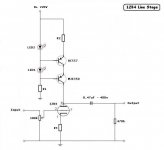
I want to use the attached circuit, but only with 17mA anode current. How do I calculate all the R values?
I only got B+ of 220V.
Can somebody please assist with some calculations for me?
I want to use the attached circuit, but only with 17mA anode current. How do I calculate all the R values?
I only got B+ of 220V.
Attachments
Hi JDeV
An extensive explanation on the calculations of CCS's is given in a PDF available at the thread on the DIYaudio CCS's boards. Although you will not be using the boards (I imagine) the explanations are still useful and will help you to get to the 17mA!
Good luck, Erik
An extensive explanation on the calculations of CCS's is given in a PDF available at the thread on the DIYaudio CCS's boards. Although you will not be using the boards (I imagine) the explanations are still useful and will help you to get to the 17mA!
Good luck, Erik
How do I figure out what is the lowest value the input volume pot is able to be without compromising anything audioable?
Can I put some input transformers with 10k pot? This worked well in another linestage with ecc88.
cheers!
Can I put some input transformers with 10k pot? This worked well in another linestage with ecc88.
cheers!
Hi,
R1 is simple and is dependent on the total hfe of your transistors. The calculations in the PDF for that one doesn't always work. A value to give 500uA for 17mA is reasonable to get the LED's going and let the transistors beta do the rest.
Have a variable in series with R2 because you'll need it. Getting a fixed value to work consistently amongst different transistors will be next to impossible. Been there 😉
Cheers!
JDeV said:I want to use the attached circuit, but only with 17mA anode current. How do I calculate all the R values?
R1 is simple and is dependent on the total hfe of your transistors. The calculations in the PDF for that one doesn't always work. A value to give 500uA for 17mA is reasonable to get the LED's going and let the transistors beta do the rest.
Have a variable in series with R2 because you'll need it. Getting a fixed value to work consistently amongst different transistors will be next to impossible. Been there 😉
Cheers!
tubelab.com said:I have used the 12B4 before, usually as a driver, before I discovered PowerDrive. If you like 12B4's you should check out the 7233. It has a plate resistance of 230 ohms, about one fourth that of the 12B4.
These were used as series regulators. They were also used in HP sweep generators as the sweep source. May be overkill for a line stage.
Don't be tellin' folks about the 7233 tube! Now the prices are going to be even higher than they were in 2005.
ErikdeBest said:Hi JDeV
An extensive explanation on the calculations of CCS's is given in a PDF available at the thread on the DIYaudio CCS's boards. Although you will not be using the boards (I imagine) the explanations are still useful and will help you to get to the 17mA!
Good luck, Erik
O.K., let me try: (With ref. to my circuit above)
For R1: I=5mA
R1=220/0.005=44k P=220x0.005=1.1W
For R2: I=17mA
R2=1/0.017=58.8ohm P=1x0.017=0.017W
For R3:
A ha, the manual does not say what voltage I will get after the cathode, how do I do this one ?
ErikdeBest said:An extensive explanation on the calculations of CCS's is given in a PDF available at the thread on the DIYaudio CCS's boards.
Could you point us to this PDF?
TIA
korneluk said:
Could you point us to this PDF?
TIA
It is supposed to be here:
diyAudio-CCS-beta2.pdf
That link did not work , then I found it also here:
Other-link-to-diyAudio-CCS-beta2.pdf
This link did work
For a 20mA plate current, what would be a good cathode resistor to use? I'm looking at the curves and it seems like grid-cathode of -20v is quite linear, but the curves only show in 10v resolution.
I am now using a 500ohm on cathode, 100k for LED current and 50ohm on emitter of BC557. This gives me 20mA on the cathode. The sound is just mindblowing, never heard my equipment sound like this before. I got only one concern, the CCS is build on a heatsink, not too small -still it is getting extremely hot, cannot keep finger on the heatsink for more then 5seconds, is this normal?
I also get quit alot of "hisss" on the speakers and if I tap the volume knob or the chassis , I can can hear it on the speakers.
How can I solve these problems? I did fit a 500ohm between POT and grid, did make no differance.
Before this circuit I tried just normal resistors on anode and cathode, did not get these problems then.
Hi,
Mmmmm, cutting it close methinks.
I use a CPU heatsink. Low profile and works awesome.
Cheers!
JDeV said:...the CCS is build on a heatsink, not too small -still it is getting extremely hot, cannot keep finger on the heatsink for more then 5seconds, is this normal?
Mmmmm, cutting it close methinks.
I use a CPU heatsink. Low profile and works awesome.
Cheers!
Do you guys expose the heatsink on top of the chassis? I did that and mine is not that hot, I could probably leave my hand on it for a couple of minutes (if not indefinitely)... 🙂
Both my MJE350's are on the same heatsink.
Heatsink are: 50mm long, 20mm high and 20mm wide. It is inside enclosure.
Maybe I must put a small fan on it.
Heatsink are: 50mm long, 20mm high and 20mm wide. It is inside enclosure.
Maybe I must put a small fan on it.
Help needed with 12b4 psu, I am on a mac and therefore unable to use Duncan amps PSU calculator. So guys I am humbly asking for some help in order to have the optimum B+ before a C4S. As I am building this from the ground up I have only a lundahl LL1651 (42Ω/500v, .43A, 4X 0.1Ω/6.6v, 3.1A) and some bottle head C4S's.
I have poured over every available schematic here and on google, however without the availability of PSU calculator, I am unable with my experience to create a suitable PSU supply and subsequently the overall schematic.
I have thought long and hard for not wanting to appear as some sort of freeloader before posting this. With all of the experience of the people in this thread I am hoping that someone is willing to give me a hand in creating my first 12b4 line stage.
Thank you for your time
Greg
JDeV said:I am now using a 500ohm on cathode, 100k for LED current and 50ohm on emitter of BC557.......
Hi JDeV,
The heat dissipation of the MJE350 depends on the voltage drop across it. I use almost the same settings for the constant current source as you with a B+ of 220V DC. The anode voltage is 150V.
I chose a cathode resistor (not bypassed) of 975 Ohm, made out of four 3K9 (0,6W) good quality metal film resitors in parallel.
The interesting thing is, that I also experienced hiss when I only used one single carbon film resitor of 1k. The voltage drop across the cathode resitor is 19V.
The 12B4 tends to be quite microphonic, I had to selected two quiet tubes. The use of (expensive) teflon tube sockets might reduce the problem even more.
happy listening
Pieroh
- Home
- Amplifiers
- Tubes / Valves
- Yet another 12B4 line stage, or is the 12B4 better than the Grounded Grid.....